Air suspension type ultrasound superspeed electric spindle

An air suspension, ultra-high-speed technology, used in metal processing machinery parts, maintenance and safety accessories, metal processing equipment, etc., can solve the problems affecting the rotation accuracy and service life of the spindle, unable to achieve ultra-high-speed rotation, and safety hazards. Guaranteed service life, low rotational resistance, and no friction and wear effects

Active Publication Date: 2018-08-10
唐德祥
View PDF7 Cites 14 Cited by
  • Summary
  • Abstract
  • Description
  • Claims
  • Application Information

AI Technical Summary

Problems solved by technology

The high-speed rotation of the existing ultrasonic machining electric spindle adopts the ordinary electric spindle structure, and the bearing is used as the rotating connection part, which inevitably generates friction and heat during use. At the same time, the rotating connection of the ordinary bearing cannot meet the needs of ultra-high-speed rotation.
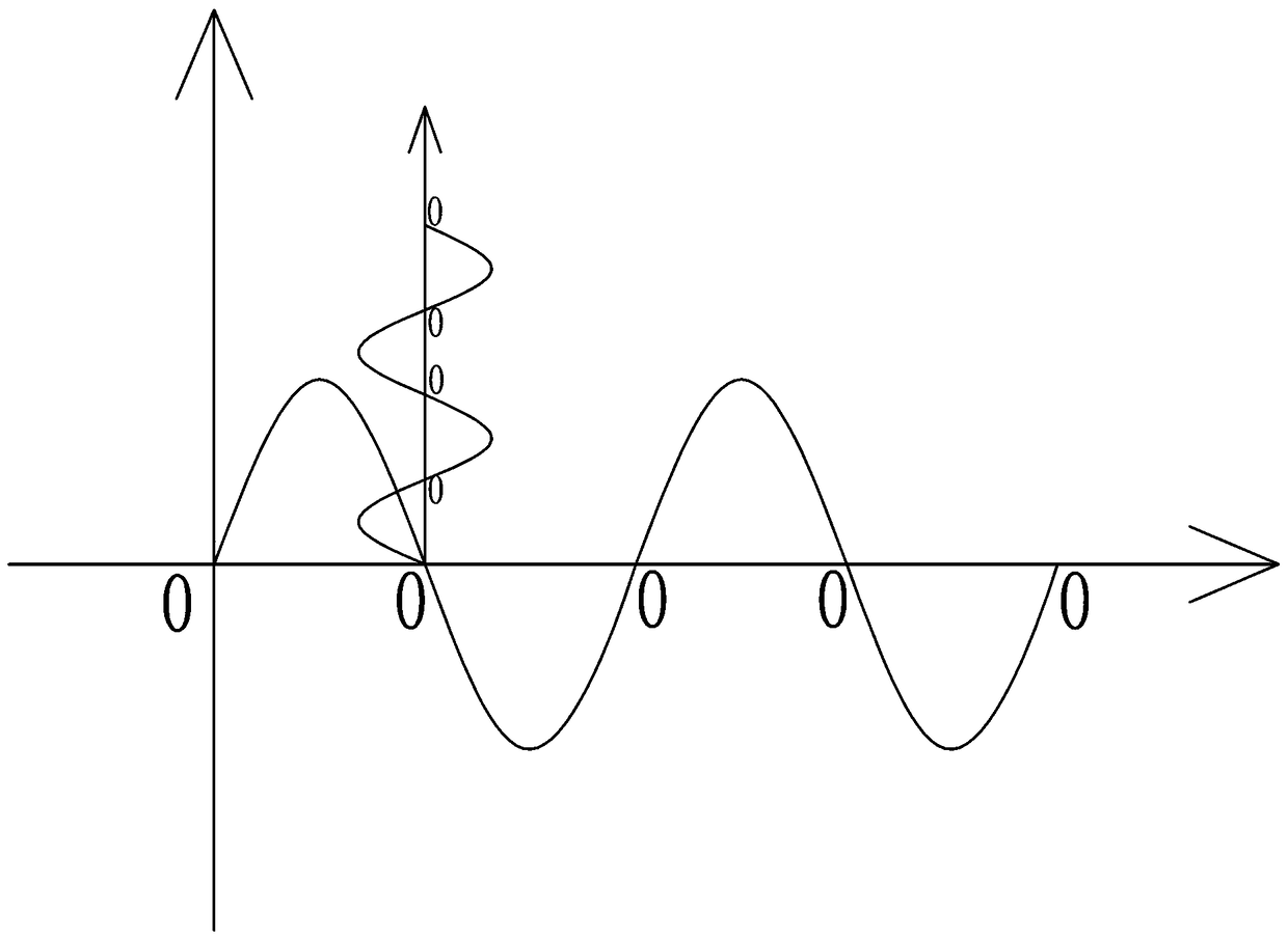
In addition, the ultrasonic machining tool is generally connected to the electric spindle through a flange. In order to prevent the vibration of the tool from being transmitted to the spindle, it is usually necessary to correspond the installation position of the flange to the zero point position of the ultrasonic vibration waveform, as shown in figure 1 As shown, the amplitude of the zero point position of the ultrasonic vibration waveform is 0, so there is no vibration at this position, that is, the flange does not vibrate. However, the zero point po...

Method used


Image

  • Air suspension type ultrasound superspeed electric spindle
  • Air suspension type ultrasound superspeed electric spindle
  • Air suspension type ultrasound superspeed electric spindle

Examples


Embodiment Construction

[0027]The present invention will be further described in detail below in conjunction with the accompanying drawings.

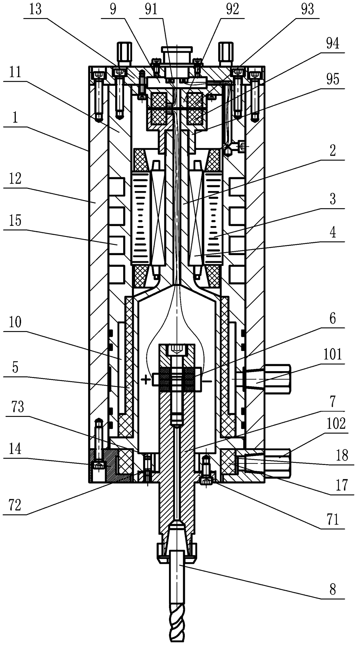
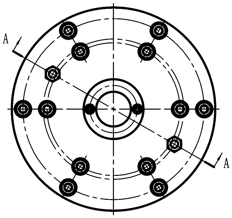
[0028] Such as figure 2 , image 3 and Figure 4 As shown, an air-suspended ultrasonic ultra-high-speed electric spindle includes a housing 1, a spindle 2, a stator 3, a rotor 4, an upper rotating support block 5, a transducer 6, a horn 7 and a tool 8. The housing 1 includes an inner cylinder 11, an outer cylinder 12, an upper end cover 13 and a lower end cover 14. The inner cylinder 11 is installed in the outer cylinder 12, and the upper ends of the inner cylinder 11 and the outer cylinder 12 are tightly connected to the upper end cover 13. The lower end cover 14 is firmly connected with the lower end of the outer cylinder 12, and the upper end cover 13 is provided with a junction block 9, and the junction block 9 includes an external wire terminal 91, an upper induction seat 92, an upper winding 93. The lower winding 94 and the lower induction seat 95, t...


PUM


Abstract

The invention relates to an air suspension type ultrasound superspeed electric spindle. A hollow spindle is installed in a shell in a penetrating manner, a rotor is connected to the middle portion ofthe spindle and corresponds to a stator, an upper rotating supporting block and a lower rotating supporting block are arranged between the lower portion of the shell and the spindle, an upper air supply channel is arranged between the upper rotating supporting block and the shell, a lower air supply channel is arranged between the lower rotating supporting block and the shell, an air inlet communicates with the upper air supply channel and the lower air supply channel, an amplitude-change pole and an energy converter are installed at the lower portion of the spindle in a penetrating manner, the lower end of the amplitude-change pole is connected with a cutter, and the upper rotating supporting block and the lower rotating supporting block are each formed by porous materials. After high-pressure air is led into the rotating supporting blocks made of the porous materials, air suspension of the spindle is achieved, the spindle rotates at the ultra-high speed, a one-face-two-pin positioning manner is used for achieving positioned connection of the ultrasonic machining amplitude-change pole and the spindle, a flange is in the not vibration state, ultrasound vibration is prevented from being transmitted to the spindle, and the superspeed stable rotation of the spindle is guaranteed.

Description

Technical field: [0001] The invention belongs to the technical field of ultrasonic processing and manufacturing, and in particular relates to an air-suspended ultrasonic ultra-high-speed electric spindle. Background technique: [0002] The ultrasonic electric spindle uses the tool to vibrate at high frequency in the axial direction, so that the tool rotates at high speed to cut the workpiece, which can reduce the processing resistance, improve the processing efficiency, significantly improve the processing accuracy of the processing surface, and reduce the surface roughness of the processing surface. No debris, good tool lubrication and cooling, good tool self-sharpening, no need for repeated grinding, greatly prolonging tool life, suitable for processing hardened steel, strengthened glass, quartz crystal, ceramics and semiconductor parts . The high-speed rotation of the existing ultrasonic machining electric spindle adopts the ordinary electric spindle structure, and the b...

Claims


Application Information

Patent Timeline
IPC IPC(8): B23B19/02B06B1/06B23Q11/12
Inventor 唐军
Owner 唐德祥
Why Eureka
Try Eureka