
A kind of H-shaped steel turn over welding method and its auxiliary tooling

A technology for auxiliary tooling and H-beam, applied in auxiliary devices, welding/cutting auxiliary equipment, auxiliary welding equipment, etc., can solve the problems of increased correction work, waste of cost, deformation of H-beam, etc., to ensure stable assembly, labor-saving and convenient operation Effect

Active Publication Date: 2021-03-02
CSSC HUANGPU WENCHONG SHIPBUILDING COMPANY
View PDF9 Cites 0 Cited by
  • Summary
  • Abstract
  • Description
  • Claims
  • Application Information

AI Technical Summary

Problems solved by technology

[0003] In the prior art, after the assembly of the H-shaped steel on the tire frame is completed, the assembled H-shaped steel is hoisted and placed on an inclined welding support for submerged arc welding. H-shaped steel turns over to another weld for welding, and an H-shaped steel beam has a total of 4 welds, that is, to complete the welding construction of an H-shaped steel beam, it needs to turn over 4 times. A large number of turning and hoisting operations will not only easily cause H The deformation of the section steel increases the follow-up correction work, reduces the overall production quality, and increases the labor intensity of the lifting personnel, resulting in cost waste
In addition, the assembly and welding of H-beams are carried out at different stations, that is, the assembled H-beams need to be hoisted to the welding station, and after moving the stations, it is necessary to reposition or add shape-retaining reinforcement before proceeding to the next step , the process is cumbersome and complicated, which makes the assembly and welding of H-beams inefficient

Method used


Image

  • A kind of H-shaped steel turn over welding method and its auxiliary tooling
  • A kind of H-shaped steel turn over welding method and its auxiliary tooling
  • A kind of H-shaped steel turn over welding method and its auxiliary tooling

Examples


Embodiment Construction

[0039] The following will clearly and completely describe the technical solutions in the embodiments of the present invention with reference to the accompanying drawings in the embodiments of the present invention. Obviously, the described embodiments are only some, not all, embodiments of the present invention. Based on the embodiments of the present invention, all other embodiments obtained by persons of ordinary skill in the art without creative efforts fall within the protection scope of the present invention.

[0040] It should be understood that the terms "first", "second", etc. are used in the present invention to describe various information, but these information should not be limited to these terms, and these terms are only used to distinguish information of the same type from each other. For example, "first" information may also be referred to as "second" information without departing from the scope of the present invention, and similarly, "second" information may al...


PUM


Abstract

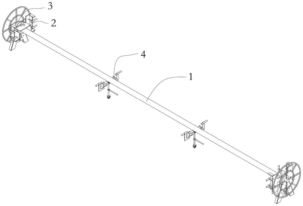
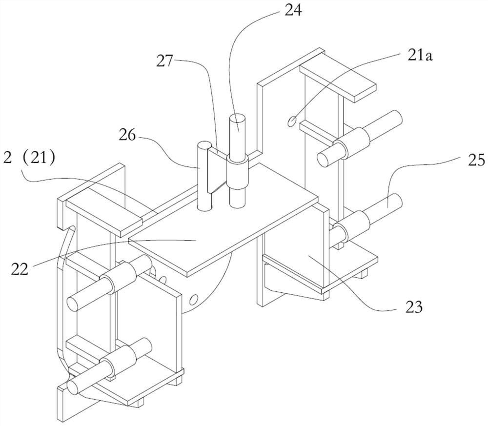
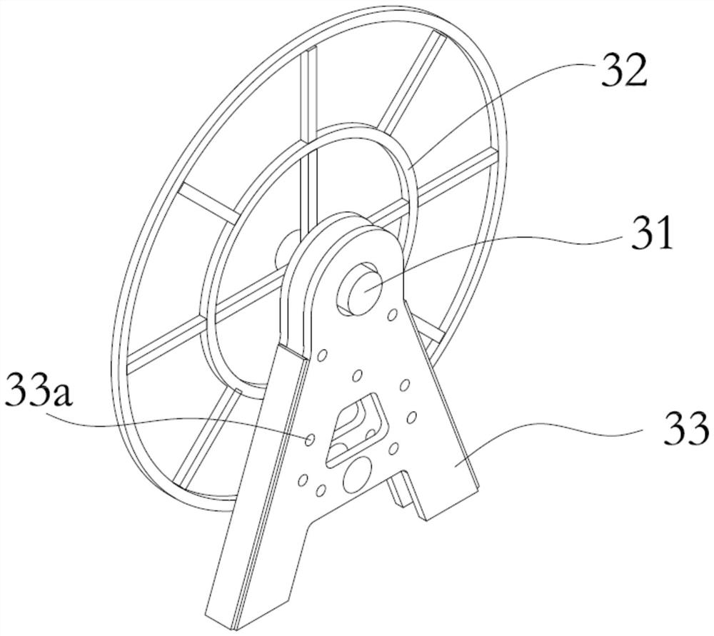
The invention provides an H-shaped steel turn-over and welding auxiliary tooling, which includes a connecting steel pipe, a positioning device, an end fixing device and a supporting device. The bottom is connected with the ground cow, the end fixing device is provided with a rotating shaft, each rotating shaft and the connecting steel pipe are connected with the positioning device, and the supporting device can be movably arranged at the middle and lower part of the connecting steel pipe; the positioning device is provided with a first positioning hole, and the end The fixing device is provided with a second positioning hole, and the positioning device is rotated and fixed at different angles through a bolt between the second positioning hole and the first positioning hole. In order to achieve the same purpose, the present invention also provides a method for turning over and welding an H-shaped steel. Adopting the H-shaped steel turn-over welding method and its auxiliary tooling of the technical solution of the present invention enables assembly and welding to be performed at the same station, reduces subsequent H-shaped steel correction work, improves H-shaped steel assembly and welding efficiency, and saves construction costs.

Description

technical field [0001] The invention relates to the technical field of assembly and welding of H-shaped steel, in particular to a method for turning over and welding an H-shaped steel and its auxiliary tooling. Background technique [0002] For a welded steel beam with an "H-shaped" section, the H-shaped steel includes a web and two panels located on the left and right sides of the web, and the cross-section of the entire H-shaped steel presents an "H-shaped". [0003] In the prior art, after the assembly of the H-shaped steel on the tire frame is completed, the assembled H-shaped steel is hoisted and placed on an inclined welding support for submerged arc welding. H-shaped steel turns over to another weld for welding, and an H-shaped steel beam has a total of 4 welds, that is, to complete the welding construction of an H-shaped steel beam, it needs to turn over 4 times. A large number of turning and hoisting operations will not only easily cause H The deformation of the se...

Claims


Application Information

Patent Timeline
Patent Type & Authority Patents(China)
IPC IPC(8): B23K9/18B23K9/235B23K37/047
CPCB23K9/18B23K9/235B23K37/047
Inventor 梁俊民梁剑明何开平
Owner CSSC HUANGPU WENCHONG SHIPBUILDING COMPANY
Learn More