
Method for manufacturing side main beam with suspension centre penetrating through I shape weathering resistance steel

A production method and technology of weathering steel, applied in bridges, buildings, etc., can solve problems such as large amount of welding, complex structure of side girders, and high welding process requirements

Active Publication Date: 2018-08-10
CHINA RAILWAY SHANQIAO GRP CO LTD
View PDF6 Cites 1 Cited by
  • Summary
  • Abstract
  • Description
  • Claims
  • Application Information

AI Technical Summary

Problems solved by technology

[0002] The steel-concrete composite beam is becoming a popular structural form for long-span bridges. The side main girder is connected with the beam and the air nozzle as a whole. The structure of the side main girder is complicated and requires high manufacturing precision. The side main girder is made of weathering steel, which requires high welding process and requires a large amount of welding.

Method used


Image

  • Method for manufacturing side main beam with suspension centre penetrating through I shape weathering resistance steel
  • Method for manufacturing side main beam with suspension centre penetrating through I shape weathering resistance steel
  • Method for manufacturing side main beam with suspension centre penetrating through I shape weathering resistance steel

Examples


Embodiment

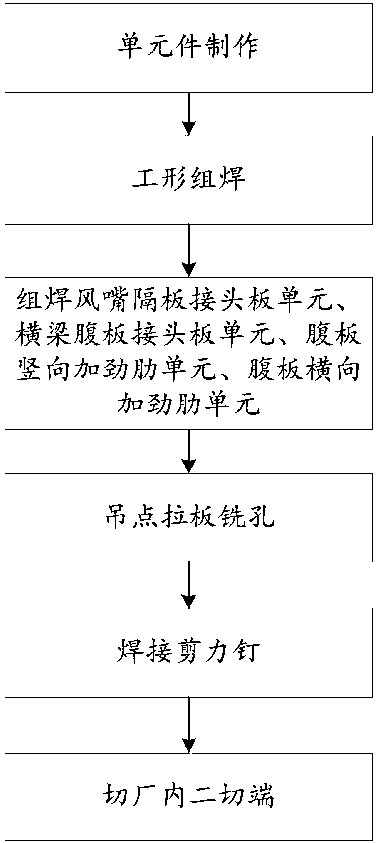
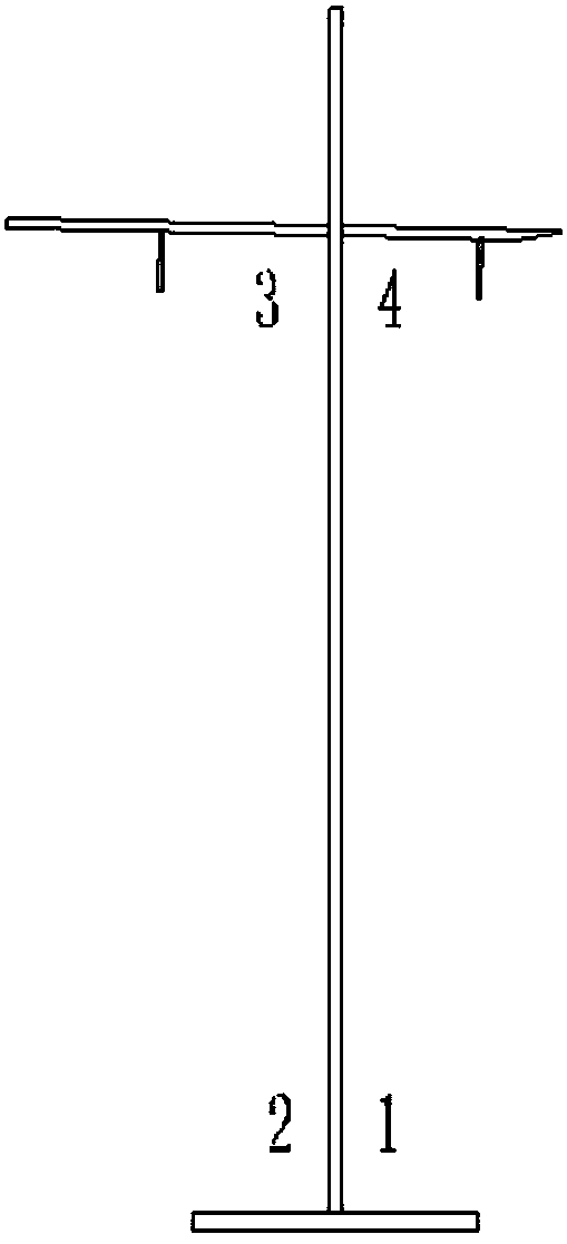
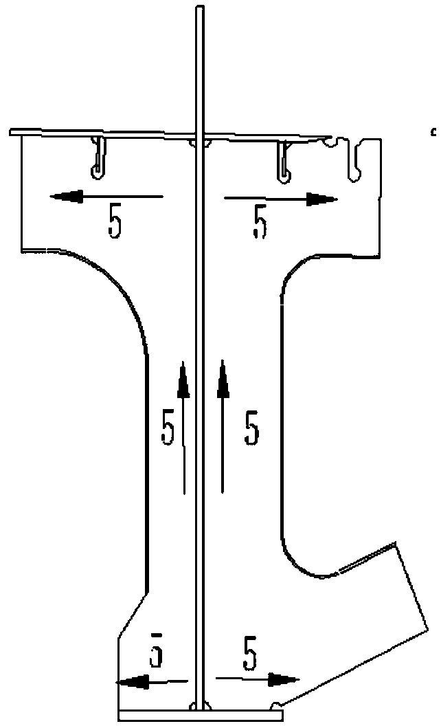
[0035] see figure 1 , figure 2 , image 3 , Figure 4 , Figure 5 , Image 6 , Figure 7 , Figure 8 , Figure 9 , Figure 10 , Figure 11 , a method for manufacturing the main girder with the I-shaped weathering steel side with the lifting point pierced by the embodiment of the present invention, such as figure 1 As shown, the method includes the production of unit elements, and each unit element is manufactured according to the design requirements, and the unit elements include a web unit, an upper horizontal plate unit, a lower horizontal plate unit, a nozzle partition joint plate unit, and a beam web joint plate unit, web vertical stiffener unit, and web transverse stiffener unit; when the web unit is manufactured, the steel plate is first cut to the required size, and after cutting, it is flattened and corrected, and the welded edge is planed with a planer, and the thick plate Use a milling machine to mill the slope, process the groove, assemble and weld, and p...


PUM


Abstract

The invention discloses a method for manufacturing a side main beam with a suspension centre penetrating through I shape weathering resistance steel. The method comprise the steps that element piecesare manufactured; I shape assembling and welding is carried out; an air nozzle separation plate joint plate element, cross beam web plate joint plate element, web plate vertical stiffening rib elementand web plate transverse stiffening rib element are assembled and welded; a lifting point pulling plate is subjected to hole milling; shear nails are welded; the center of the hanging point pulling plate is used as the base to mark the line after the shear nails are welded; the in-plant second tangency end is cut, and the in-plant base ends of an upper horizontal plate element, a web plate element and a lower horizontal plate element are cut. According to the method, each assembly element is resolved in a modularized mode, the assembling and welding sequence is reasonable, the welding processis advanced, the degree of automation is high, the deformation caused by welding is small, and the assembling precision is high; and rod pieces are assembled by the forward-calculation method, so that the number of turning over is reduced, the efficiency and precision of assembling and welding are improved, and good economic results are obtained.

Description

technical field [0001] The invention relates to the technical field of large-span steel-concrete combined beams, in particular to a method for manufacturing a main girder with an I-shaped weather-resistant steel edge through which lifting points pass. Background technique [0002] The steel-concrete composite beam is becoming a popular structural form for long-span bridges. The side main girder is connected with the beam and the air nozzle as a whole. The structure of the side main girder is complex and requires high manufacturing precision. The side main girder is made of weathering steel with high welding process requirements and a large amount of welding, which is difficult and difficult. Therefore, a reasonable welding sequence and welding process is the key to ensure the geometric accuracy of the rod. Contents of the invention [0003] The invention provides a method for manufacturing a main girder with an I-shaped weather-resistant steel side through which a hanging...

Claims


Application Information

Patent Timeline
IPC IPC(8): B23P15/00E01D1/00
CPCB23P15/00E01D1/00
Inventor 李华冰尹春明张帆孙树松乔新旺
Owner CHINA RAILWAY SHANQIAO GRP CO LTD
Learn More