Welding method of automobile brake gear ring and device using method

A technology for automobile braking and welding devices, applied in auxiliary devices, welding equipment, auxiliary welding equipment, etc., can solve the problems of uneven welding angle height, deviation of welding seam position, large deformation of gear ring, etc., and achieve reasonable welding sequence. , The effect of preventing welding deformation and improving efficiency

Active Publication Date: 2015-05-20
宁波骏腾发自动化设备有限公司
View PDF4 Cites 0 Cited by
  • Summary
  • Abstract
  • Description
  • Claims
  • Application Information

AI Technical Summary

Problems solved by technology

[0003] With the existing welding method, after the gear ring is welded, there will often be problems such as deviation of the weld position, uneven welding angle, and low welding efficiency. What is more serious is that the gear ring is deformed after welding, and the flatness exceeds 0.3mm. Secondary processing is required, which brings great problems to subsequent processes

Method used


Image

  • Welding method of automobile brake gear ring and device using method
  • Welding method of automobile brake gear ring and device using method
  • Welding method of automobile brake gear ring and device using method

Examples


Embodiment Construction

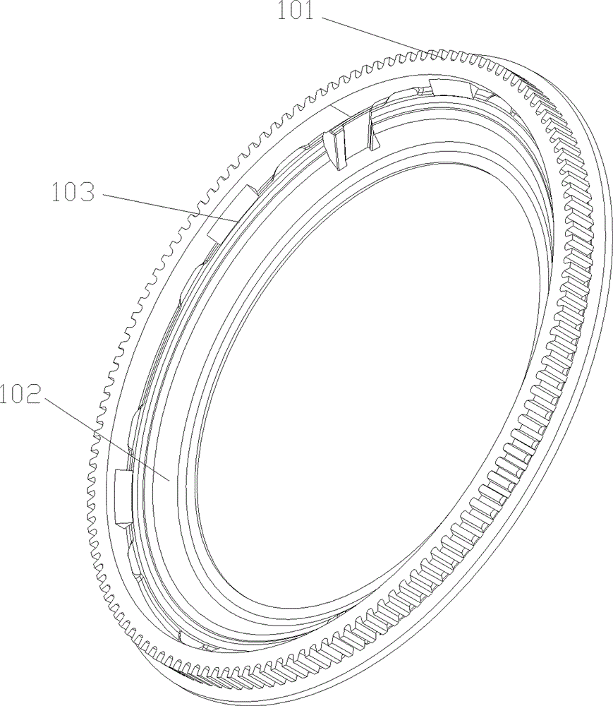
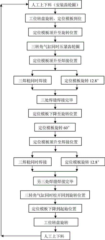
[0038] like figure 2 Shown, a kind of automobile brake gear ring welding method comprises the following steps:

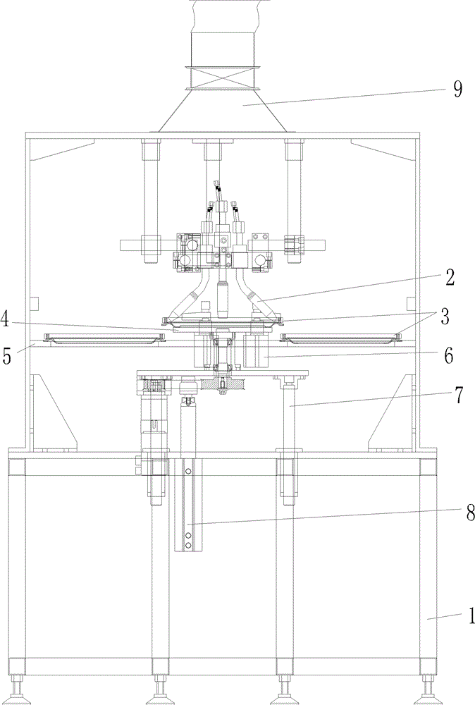
[0039] A) Manual loading and unloading, place the car brake gear ring (including the ring gear and cover plate) on the corresponding positioning hole of the station turntable, the station turntable rotates, driving the gear ring to rotate to the welding station, at this time, the positioning template In the starting position, the positioning template is located directly below the positioning hole, that is, directly below the welding torch, and the size of the positioning template matches the size of the positioning hole, that is, the positioning template can pass through the positioning hole;

[0040] B) The positioning template rises to the rotating position through the jacking cylinder. At this time, the gear ring is also located on the positioning template, and the gear ring is driven by the positioning template to rise to the rotating position together; at this...


PUM


Abstract

The invention relates to a welding method of automobile brake gear rings and a device using the method. The device comprises a stand, a positioning template, three welding guns, three corner cylinders, a jacking cylinder, a servo motor and a PLC (Programmable Logic Controller) control circuit, wherein the PLC control circuit is respectively and electrically connected with the welding guns, the corner cylinders, the jacking cylinder and the servo motor; connecting lines of welding nozzles of the three welding guns with circle centers of the automobile brake gear rings positioned on the positioning template are at 120 DEG to one another, connecting lines of the three corner cylinders with the circle centers of the gear rings are at 120 DEG to one another. The welding method and the device using the method disclosed by the invention have the advantages of even welding seams, even welding fillet height, small deformation after welding and high welding efficiency.

Description

technical field [0001] The invention relates to welding technology, in particular to an automobile brake gear ring welding method and a device using the method. Background technique [0002] like figure 1 As shown, it is a structural schematic diagram of the gear ring of an automobile brake. The gear ring includes a ring gear 101 and a cover plate 102. The ring gear 101 and the cover plate 102 are welded to form a finished gear ring. At present, the welding method of the gear ring of the automobile brake is mainly the automatic MIG / MAG welding method of double welding torches. The center of the circle is on the same straight line, and then use the positioning template, jacking cylinder, corner cylinder, and servo motor to lift and rotate the gear ring to complete the welding. [0003] With the existing welding method, after the gear ring is welded, there will often be problems such as deviation of the weld position, uneven welding angle, and low welding efficiency. What is...

Claims


Application Information

Patent Timeline
Patent Type & Authority Patents(China)
IPC IPC(8): B23K37/047B23K37/00
Inventor 刘学明周之晨
Owner 宁波骏腾发自动化设备有限公司
Why Eureka
Try Eureka