Method and device for calculating gain in digital relay device

A digital relay and equipment technology, applied in radio transmission systems, electrical components, transmission systems, etc., to achieve the effects of reducing co-frequency or adjacent frequency interference, improving coverage, and reducing invalid gain

Inactive Publication Date: 2018-08-10
SICHUAN DAJTECHNOLOGY CO LTD
View PDF12 Cites 2 Cited by
  • Summary
  • Abstract
  • Description
  • Claims
  • Application Information

AI Technical Summary

Problems solved by technology

[0007] Since the wireless digital relay equipment must be a low-latency device, if the uplink and downlink path loss calculati

Method used


Image

  • Method and device for calculating gain in digital relay device
  • Method and device for calculating gain in digital relay device
  • Method and device for calculating gain in digital relay device

Examples


Embodiment Construction

[0036] The present invention will be further described in detail below in conjunction with examples, but the embodiments of the present invention are not limited thereto.

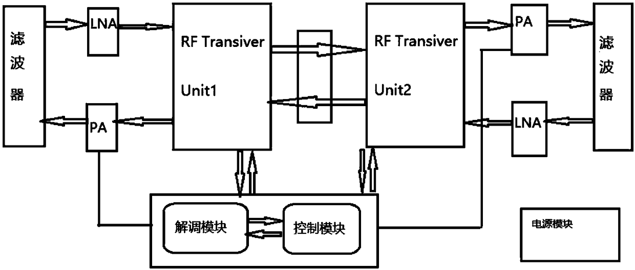
[0037] In one embodiment, a wireless digital relay device includes:

[0038] The wireless digital amplifying device includes a radio frequency transceiver unit, which has a digital amplifier that can be adjusted according to the configuration, and the output power of the transmitting port of the radio frequency transceiver unit can guarantee a certain dynamic range.

[0039] The wireless digital relay equipment has a control unit, and the control unit is used for data transmission management between two radio frequency transceiver modules. In the present invention, it is mainly used to realize the path loss learning algorithm, and calculate the uplink and downlink channel gain value list according to the path loss situation. And configure the gain to the corresponding radio frequency transceiver unit.

[0...


PUM


Abstract

The invention discloses a method and device for calculating gain in a digital relay device. The power of a downlink channel is taken as the reference by a control unit in the digital relay device. Theamplifying gain of a wireless digital amplifier on a downlink signal is firstly obtained according to downlink coverage requirements to be taken as the reference of a target coverage; aiming at a digital relay device with a common channel modulation capability, the intensity of a pilot signal can be taken as the reference, and aiming at a digital relay device without a modulation capability, theintensity of a downlink receiving signal is taken as the reference. According to the method, the problem of power control under different coverage scenarios can be solved through the self-adaptive gain configuration of uplink and downlink channels in a digital relay device, the problems of single passing, call dropping, frequent switching and out of service area of a user when the user is paged caused by excessive low uplink and downlink power of the digital relay device are prevented, and the interference problem caused by excessive high uplink and downlink power of the digital relay device is also prevented.

Description

technical field [0001] The present invention relates to the technical field of wireless communication, in particular to a method and device for calculating gains in digital relay equipment that can be applied in different scenarios. Background technique [0002] Since the wireless signal attenuates with the increase of the propagation distance, and in different environments, the occlusion, reflection, refraction and absorption of buildings or plants will also cause the wireless signal to attenuate rapidly in some scenarios, so in The cell edge in the wide coverage area or the deep indoor coverage area will lead to insufficient signal strength and poor user communication performance. [0003] In an FDD (Frequency Division Duplex, Frequency Division Duplex) system, uplink signals and downlink signals use different frequency points respectively, and a frequency division duplex mode is adopted. Different frequency bands may be subject to different degrees of fading during space...

Claims


Application Information

Patent Timeline
IPC IPC(8): H04B7/155
CPCH04B7/15535H04B7/15578
Inventor 田华王国光
Owner SICHUAN DAJTECHNOLOGY CO LTD
Why Eureka
Try Eureka