Eureka AIR delivers breakthrough ideas for toughest innovation challenges, trusted by R&D personnel around the world.

Nonstandard guide blade machining device and machining method

A technology of guide vanes and processing devices, which is applied in positioning devices, metal processing equipment, metal processing mechanical parts, etc., can solve the problems of low positioning accuracy of processing blades, and achieve the advantages of saving manufacturing costs, accurate angular positioning, and convenient clamping. Effect

Inactive Publication Date: 2018-08-14
XI'AN POLYTECHNIC UNIVERSITY
View PDF1 Cites 0 Cited by
  • Summary
  • Abstract
  • Description
  • Claims
  • Application Information

AI Technical Summary

Problems solved by technology

[0004] The purpose of the present invention is to provide a non-standard guide vane processing device, which solves the problem of low positioning accuracy of existing processed vanes

Method used


Image

  • Nonstandard guide blade machining device and machining method
  • Nonstandard guide blade machining device and machining method
  • Nonstandard guide blade machining device and machining method

Examples


Embodiment Construction

[0030] The present invention will be described in detail below in conjunction with the accompanying drawings and specific embodiments.

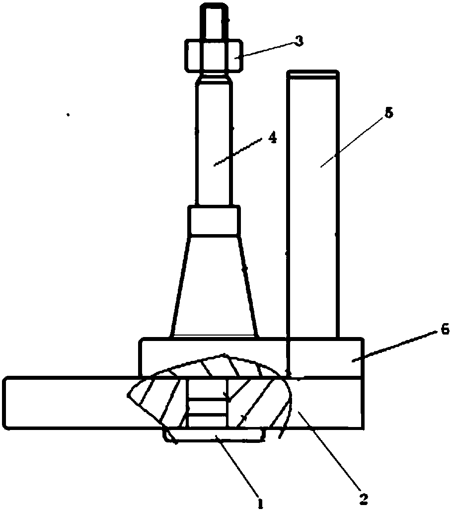
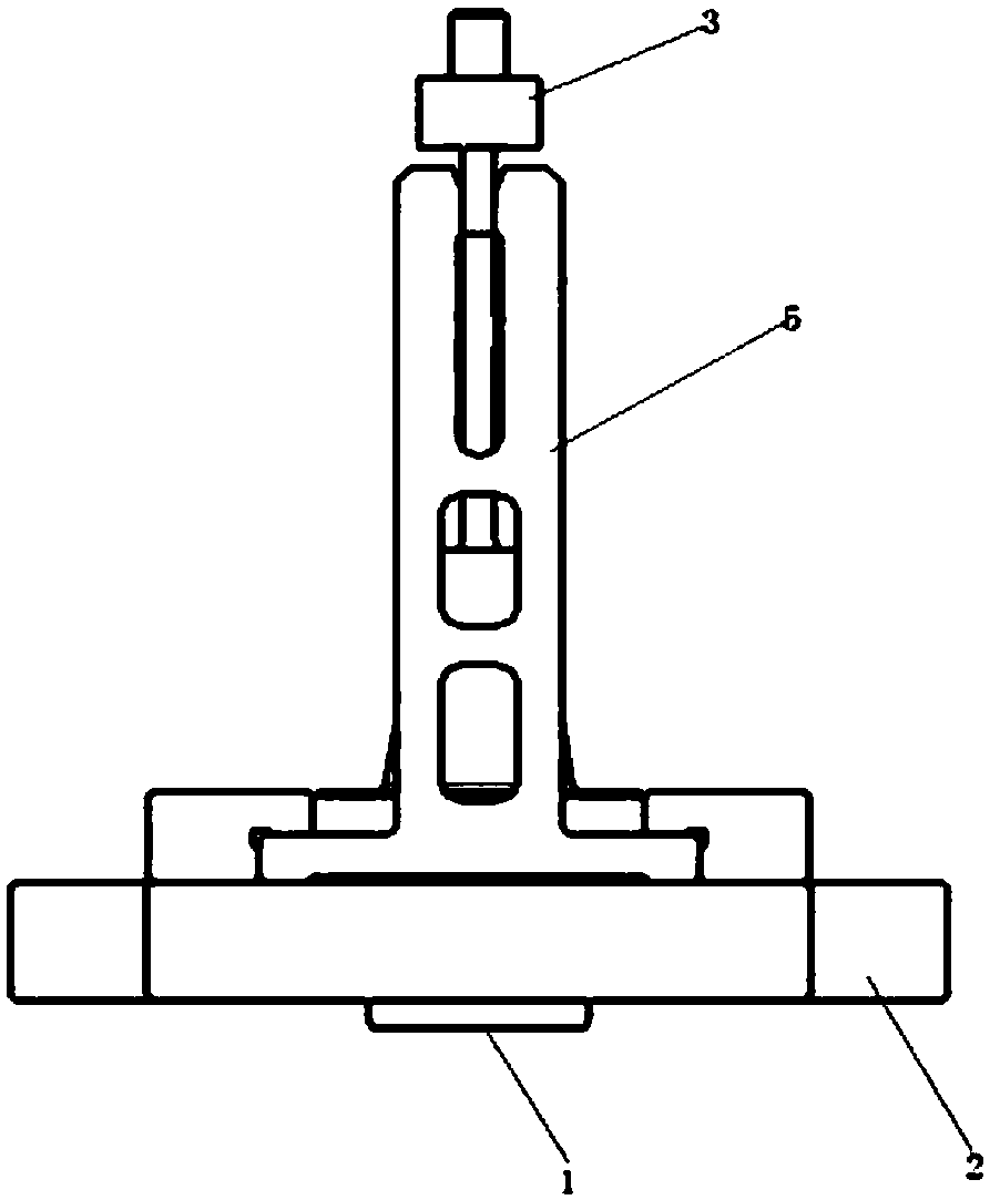
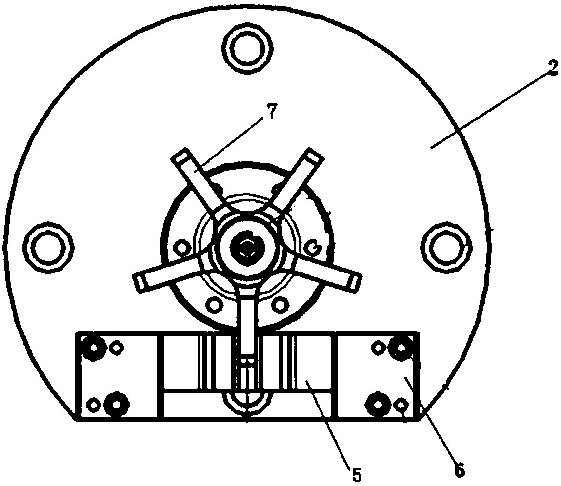
[0031] The structure of a non-standard guide vane processing device is as follows: figure 1 , Figure 4 As shown, including the flange 2, the shape of the flange 2 is that a disc cuts a segment of inferior arc along the direction perpendicular to it, and a cutting surface is formed on the flange 2, and the flange 2 is provided with a through hole at the center of the circle. two 8,

[0032] Such as figure 2 As shown, it also includes a positioning shaft 4. The positioning shaft 4 includes a cylindrical section, a tapered section, and a stepped section that are successively connected in the axial direction. Located on the other end surface of the cylindrical section, the end surface diameter of the end with the larger diameter of the tapered section is smaller than the diameter of the cylindrical section, the end with the smaller diameter ...


PUM


Abstract

The invention discloses a nonstandard guide blade machining device. The nonstandard guide blade machining device comprises a flange plate; and a second through hole is formed in the circle center of the flange plate. The nonstandard guide blade machining device further comprises a positioning shaft; the positioning shaft comprises a cylinder section, a taper section and a step section axially connected in sequence; a shaft sleeve is arranged on the step section; the bottom end of the cylinder section is radially shrunk as a shaft head; the shaft head is embedded in the second through hole; thetop surface of the flange plate is connected with a pair of rectangular guide blocks; angular positioning forks are clamped in opening grooves of the pair of guide blocks; and U-shaped grooves are formed in the end surfaces, far from the flange plate, of the angular positioning forks. The nonstandard guide blade machining device further comprises a mandrel; and one end of the mandrel is arrangedin the second through hole, and is opposite to the shaft head. The nonstandard guide blade machining device solves the problem of low blade positioning precision in traditional machining.

Description

technical field [0001] The invention belongs to the field of mechanical equipment manufacturing, and in particular relates to a non-standard guide vane processing device and processing method. Background technique [0002] The gas turbine is a rotary impeller heat engine, and the guide vane is an extremely important part on it, which directly plays the role of converting the thermal energy of steam or gas into mechanical energy. Guide vanes are not only large in number and complex in shape, but also work under high temperature and high pressure environment, and also bear relatively large centrifugal stress. Furthermore, the processing volume of guide vanes is very large, accounting for about four quarters of the total processing volume of gas turbines. One-third to one-third, so the processing requirements of guide vanes are extremely strict. The processing quality of the guide vane directly affects the operating efficiency of the unit, and the quality and life of the guide...

Claims


Application Information

Patent Timeline
Patent Type & Authority Applications(China)
IPC IPC(8): B23C3/16B23C3/18B23Q3/18
CPCB23C3/16B23C3/18B23Q3/18
Inventor 张立昌
Owner XI'AN POLYTECHNIC UNIVERSITY
Why Eureka
Eureka Blog
Learn More