
Laser trimming tab device

A technology of flat cutting and lugs, which is applied in auxiliary devices, laser welding equipment, welding/cutting auxiliary equipment, etc., can solve the problems of slow movement speed, battery pole piece shaking, and reduced suction, so as to achieve controllable waste speed, The effect of meeting the quality requirements and maintaining a flat state

Pending Publication Date: 2018-08-14
SHENZHEN HYMSON LASER INTELLIGENT EQUIP CO LTD
View PDF0 Cites 3 Cited by
  • Summary
  • Abstract
  • Description
  • Claims
  • Application Information

AI Technical Summary

Problems solved by technology

[0004] 1. The vacuum roller of the laser flat cutting component is an integral roller (the integral roller is driven by the rotation of the battery pole piece), and there will be instability during the continuous operation of the battery pole piece, which will cause the position of the tab cutting area to change. It is easy to cause problems such as laser defocusing and cutting burrs;
[0005] 2. The width of both sides of the cutting opening of the original cutting block is the same, but the laser cutting track is trapezoidal, and the opening towards the top side of the tab is larger. When cutting the top of the tab, it may collide with the cutting opening of the cutting block, resulting in deformation of the tab , there is damage to the tab; when the internal negative pressure of the cutting block increases, the side of the tab will collide with the edge of the support block, and the cutting edge will bulge due to the collision, causing the position of the pole piece to change, and the pole piece is out of focus, resulting in cutting burrs on the tab , cutting and other problems; the shape of the tab support block is small, and the support surface of the support block cannot effectively support the tab during cutting;
[0006] 3. The movement speed of the belt without motor is slow, and the waste side does not run smoothly, which leads to defocusing, cutting burrs, and continuous ear cutting. It is sucked by the round hole on the flat belt, and then brought to the waste nozzle for unified collection), the round holes on the flat belt and the vacuum roller cannot be matched one by one, and they will be misaligned, causing the gap between the belt holes to block the hole of the vacuum roller, causing suction decrease;
[0007] 4. Because the battery pole piece may be pulled by the waste material edge, the battery pole piece shakes seriously, so the existing laser flat cutting device cannot cut the battery pole piece with continuous waste material edge

Method used


Image

  • Laser trimming tab device
  • Laser trimming tab device
  • Laser trimming tab device

Examples


Embodiment Construction

[0063] The present invention will be further described below in conjunction with the accompanying drawings and specific embodiments. Terms such as "upper", "lower", "left", "right", "middle" and "one" quoted in the preferred embodiment are only for convenience of description, and are not used to limit the scope of the present invention. The scope of implementation and the change or adjustment of its relative relationship shall also be regarded as the scope of implementation of the present invention without substantive changes in technical content.

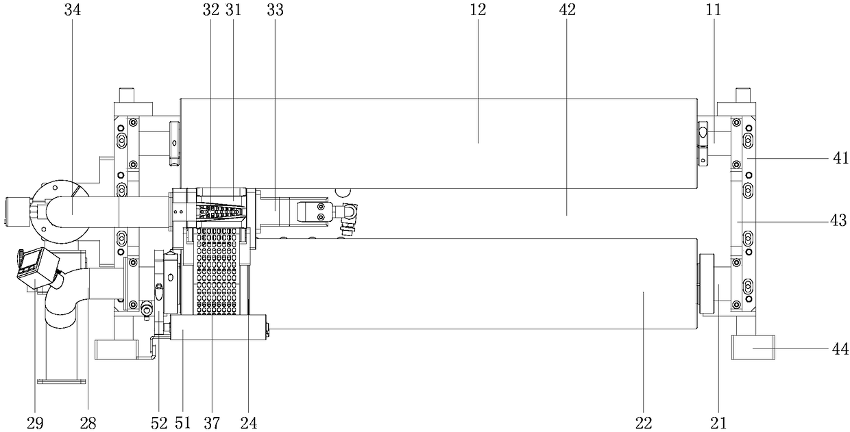
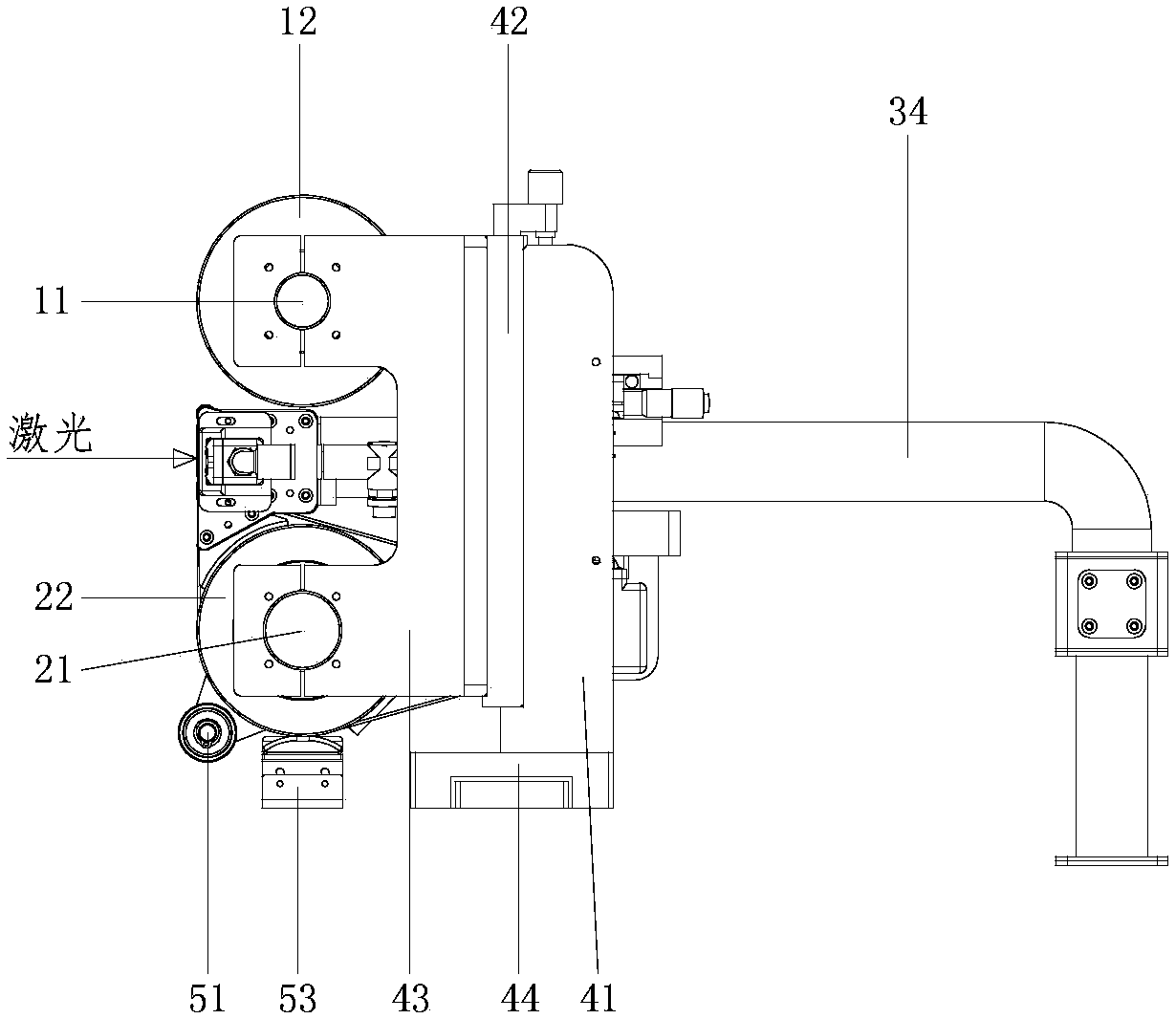
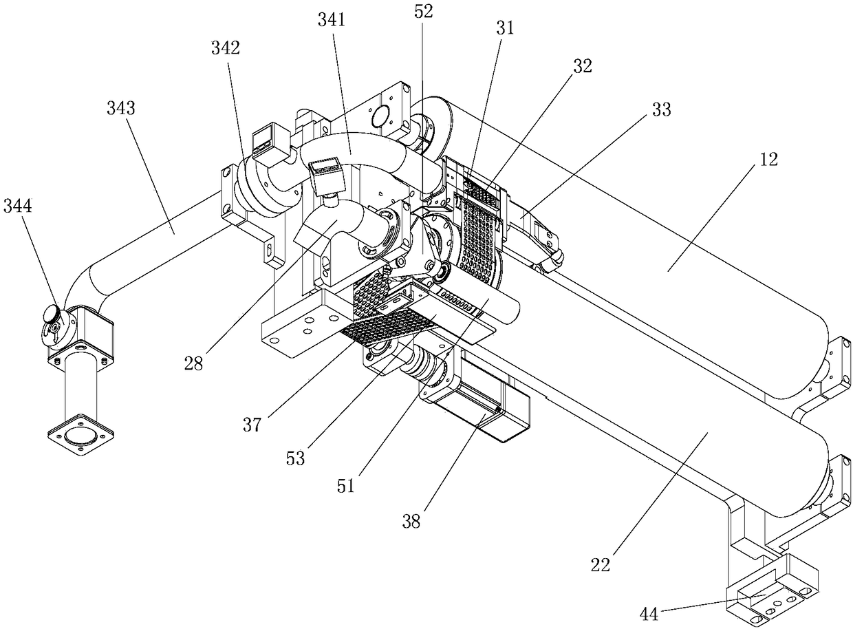
[0064] See Figure 1 to Figure 3 , a laser flat-cut lug device designed in a preferred embodiment of the present invention, which mainly includes: an upper roller assembly, a separation roller assembly, a cutting assembly, and a bracket assembly, and the upper roller assembly and the separation roller assembly are installed in parallel up and down on the bracket assembly , the cutting assembly is located on the left and right side...


PUM


Abstract

The invention discloses a laser trimming tab device. The laser trimming tab device comprises a bracket assembly, an upper roller assembly, a separation roller assembly and a cutting assembly, whereinthe upper roller assembly and the separation roller assembly are arranged on the bracket assembly in parallel up and down. The separation roller assembly is provided with two separate independent-moving rollers, namely, a non-vacuum separation roller and a vacuum separation roller which are rotatably installed with a second central shaft correspondingly. The cutting assembly is located between theupper roller assembly and the vacuum separation roller. The laser trimming tab device provides support, waste derivation and cutting dust treatment for tab cutting, the flat state of tab cutting areaof a battery plate electrode is kept, the vibration of the tab cutting area is avoided, and the quality requirement of tab cutting is required.

Description

technical field [0001] The invention relates to an auxiliary support device used for tab laser flat cutting processing. Background technique [0002] The main processing methods of battery pole pieces are die-cutting and laser cutting. Long-term use of the die-cutting process will cause quality problems such as burrs, and the tools must be replaced and maintained frequently. The cost is high, and it cannot meet the needs of battery pole pieces. The laser cutting process is a new process that has emerged in recent years, and its core advantage is that it can effectively avoid the above-mentioned shortcomings of the die-cutting process. [0003] The laser flat cutting device is a device that provides continuous support for the pole piece in the process of laser cutting the tab. It is an important process in the tab laser cutting machine. During the cutting process, the battery pole piece is in the state of continuous operation and continuous cutting. Jitter and other unstable...

Claims


Application Information

Patent Timeline
IPC IPC(8): B23K26/38B23K26/70B23K26/142B23K37/04
CPCB23K26/142B23K26/38B23K26/702B23K37/0408Y02E60/10
Inventor 张松岭赵盛宇林国栋温燕修陈胜春谷德吉马太庆张修冲管莉娜
Owner SHENZHEN HYMSON LASER INTELLIGENT EQUIP CO LTD
Learn More