

Method, system and device for controlling vehicle power device and storage medium
Patent Information
- Authority / Receiving Office
- CN · China
- Current Assignee / Owner
- TSINGHUA UNIV
- Publication Date
- 2018-08-14
Smart Images
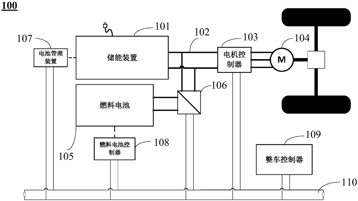
Figure 1 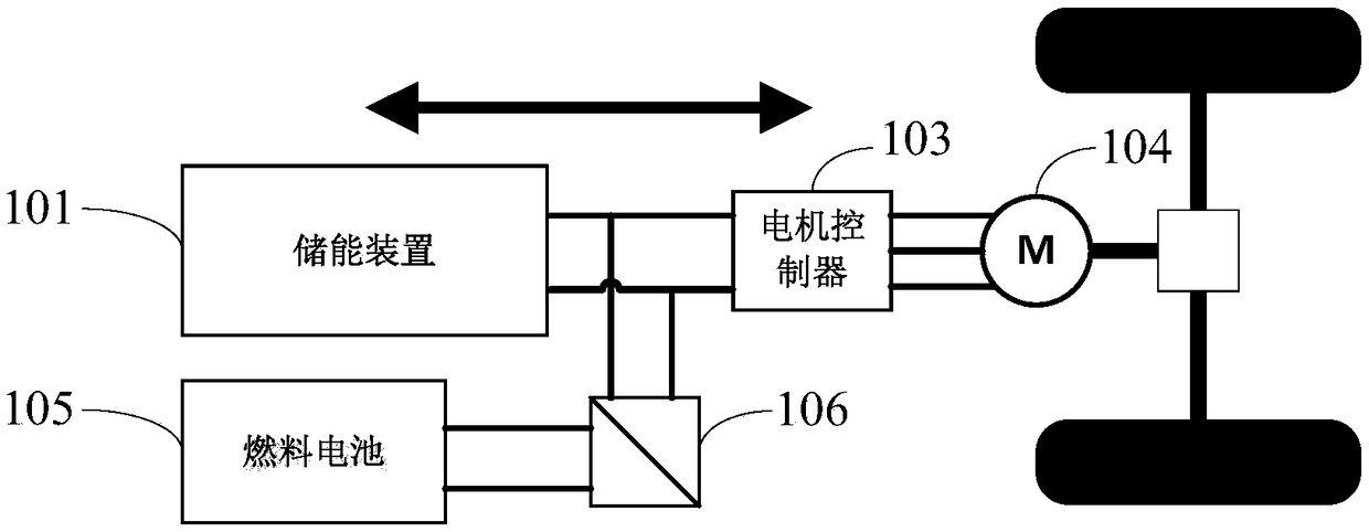
Figure 2 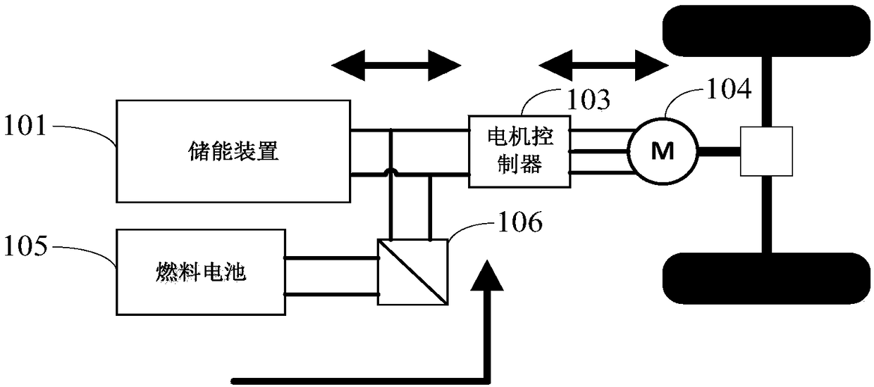
Figure 3
Abstract
Description
technical field
[0001] The invention relates to the technical field of new energy vehicles, in particular to a control method, system, device and storage medium for a power unit of an extended-range fuel cell vehicle. Background technique
[0002] Pure electric vehicles generally use power batteries as a single power source, with simple structure and high system efficiency, and have developed rapidly in recent years. However, the energy density of traditional power batteries is still low, and the mileage of pure electric vehicles is generally short, making it difficult to reach the cruising level of traditional internal combustion engine vehicles. At the same time, the charging speed of pure electric vehicles is relatively slow, which brings great inconvenience to its use.
[0003] Hydrogen-oxygen proton exchange membrane fuel cell is an electrochemical device that directly converts chemical energy into electrical energy. It has the advantages of high efficiency and zero em...