Flocculant dispenser and flocculation washer
A flocculant and dispenser technology, which is applied to other washing machines, washing devices, textiles and papermaking, etc., can solve problems such as unsatisfactory use requirements, and achieve the effect of being suitable for popularization, significant effect, and simple structure
- Summary
- Abstract
- Description
- Claims
- Application Information
AI Technical Summary
Problems solved by technology
Method used
Image

Examples
Embodiment 1
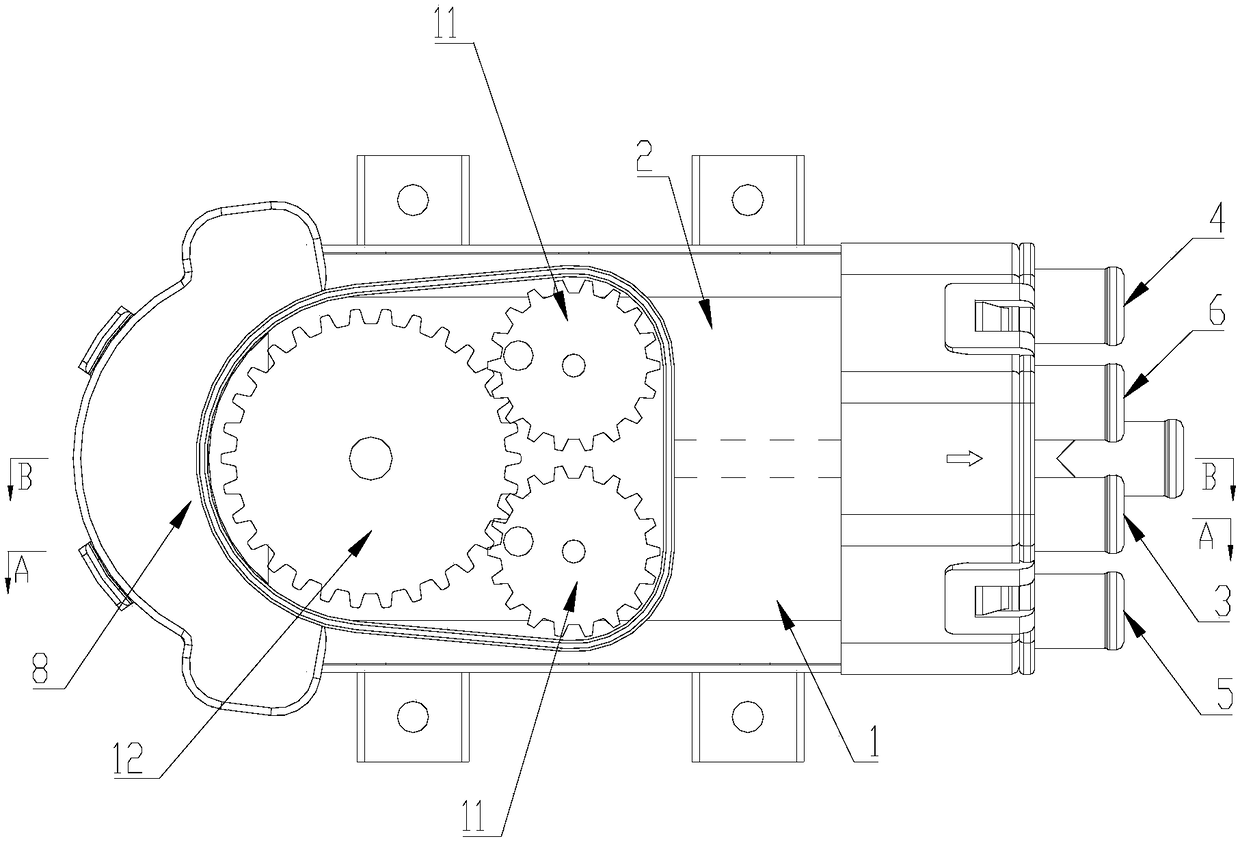
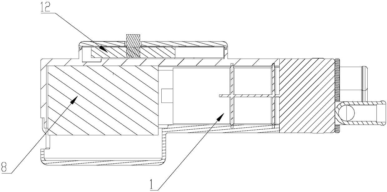
[0038] Such as Figure 1 to Figure 3 As shown, a flocculant dispenser is introduced in this embodiment, which includes two injection chambers, the first injection chamber 1 and the second injection chamber 2; The two pistons 7 are meshed with the forward and reverse motor 8 through the one-way driving device, and the output end of the forward and reverse motor 8 is rotated forward and reverse to drive different pistons 7 to reciprocate.
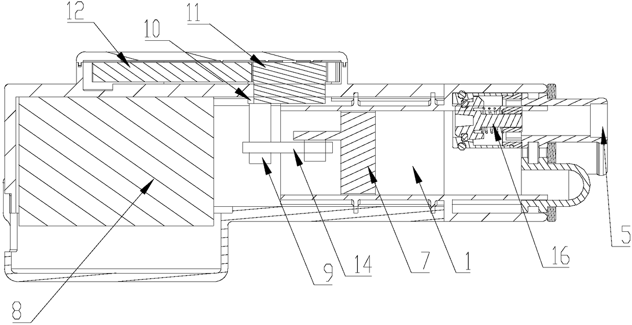
[0039] In this embodiment, the one-way driving device includes a pushing device that pushes the piston 7 to reciprocate, and the pushing device is engaged with the output end of the motor 8 through the transmission shaft 9 installed on the one-way bearing 10, so that the output end of the motor is When rotating clockwise or counterclockwise, the corresponding piston 7 is respectively driven to reciprocate.
[0040]In this embodiment, the locking directions of the two one-way bearings 10 to the transmission shaft 9 are oppositely set, so that...
Embodiment 2
[0055] Such as Figure 1 to Figure 5 As shown, this embodiment is based on the first embodiment above, and also has the following features: the first injection chamber 1 of the flocculant dispenser 100 is provided with a first liquid inlet 3 and a first liquid outlet 5, and the second injection chamber 2 The second liquid inlet 4 and the second liquid outlet 6 are provided on the top; the first liquid inlet 3, the first liquid outlet 5, the second liquid inlet 4 and the second liquid outlet 6 are respectively provided There is a one-way valve 16 for controlling the opening and closing of the corresponding pipeline. The first injection chamber 1 and the second injection chamber 2 are both airtight and sealed injection chambers, so that during the reciprocating movement of the piston 7 in the injection chamber, the pressure in the first injection chamber 1 and the second injection chamber 2 is constantly adjusted , so that the one-way valve 16 at the corresponding liquid inlet ...
Embodiment 3
[0067] Such as Figure 1 to Figure 5 As shown, this embodiment introduces a flocculation washing machine, which includes a flocculation bucket 100, two flocculant liquid storage boxes for flocculant A and flocculant B respectively, and the two liquid storage boxes are as described in the above-mentioned embodiment 1. The flocculant dispenser 200 described in or 2 is connected to the flocculation barrel 100 to inject the flocculant A and / or B into the flocculation barrel.
[0068] In this embodiment, the flocculant A liquid storage box 300 containing the flocculant A is provided with a first outlet for the flocculant A to flow out, and the first outlet communicates with the first liquid inlet 3 of the flocculant dispenser 200 through a pipeline The flocculant B liquid storage box 400 containing the flocculant B is provided with a second outlet for the flocculant A to flow out, and the second outlet is connected with the second liquid inlet 4 of the flocculant dispenser 200 thro...
PUM
 Abstract
Description
Claims
Application Information
 - R&D
- Intellectual Property
- Life Sciences
- Materials
- Tech Scout
- Unparalleled Data Quality
- Higher Quality Content
- 60% Fewer Hallucinations
Browse by: Latest US Patents, China's latest patents, Technical Efficacy Thesaurus, Application Domain, Technology Topic, Popular Technical Reports.
© 2025 PatSnap. All rights reserved.Legal|Privacy policy|Modern Slavery Act Transparency Statement|Sitemap|About US| Contact US: help@patsnap.com