
Nonuniform controllable cavity rotary sealing structure

A rotary-sealed, non-uniform technology used in non-variable-capacity pumps, leakage prevention, components of pumping devices for elastic fluids, etc., can solve the problem of fine control, neglect of effective stiffness, overall effective damping of shafting and The effective stiffness deviates from the stable operating range, etc., to achieve good sealing performance, improve operating efficiency and shaft stability, and enhance stability.

Active Publication Date: 2018-08-14
XI AN JIAOTONG UNIV
View PDF3 Cites 2 Cited by
  • Summary
  • Abstract
  • Description
  • Claims
  • Application Information

AI Technical Summary

Problems solved by technology

This is mainly due to the fact that traditional honeycomb seals, hole-type seals and bag-type seals and other damping and sealing structures often take the maximum effective damping as the design goal, while ignoring the effective stiffness, and it is impossible to achieve fine control of effective damping and effective stiffness. The overall effective damping and effective stiffness of the shafting deviate from the stable operating range

Method used


Image

  • Nonuniform controllable cavity rotary sealing structure
  • Nonuniform controllable cavity rotary sealing structure
  • Nonuniform controllable cavity rotary sealing structure

Examples


Embodiment Construction

[0041] The present invention will be further described in detail below in conjunction with the accompanying drawings and technical principles.

[0042] Concrete structure of the present invention is referring to accompanying drawing, and design train of thought is as follows:

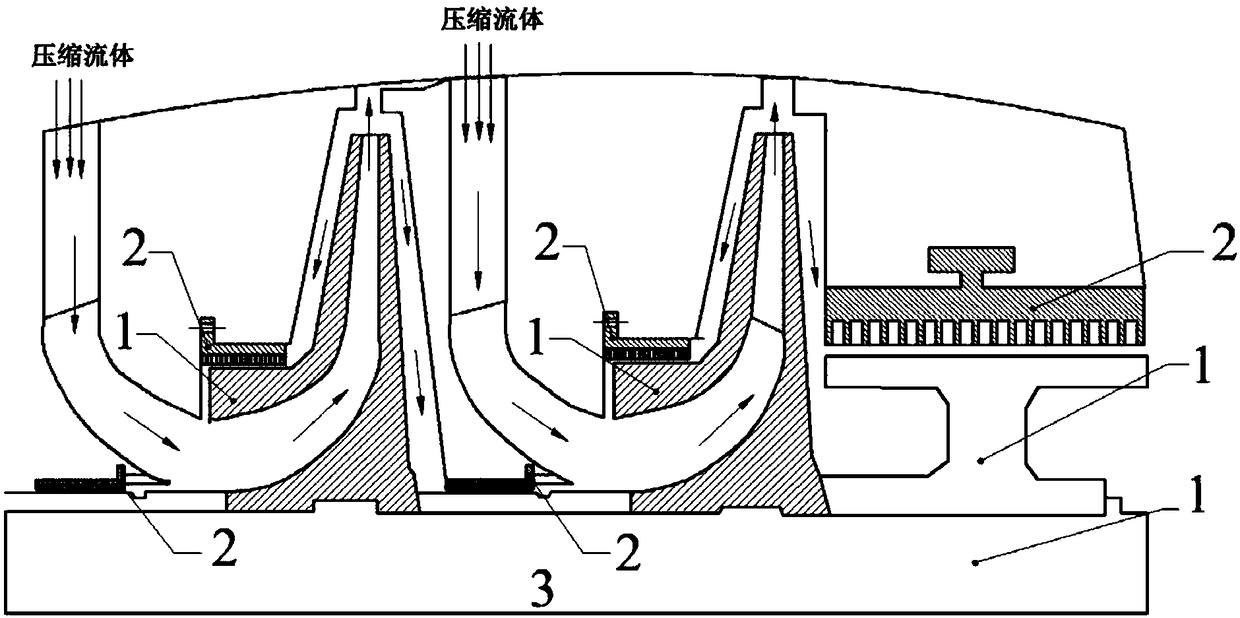
[0043] see figure 1 , the present invention provides a non-uniform controllable cavity rotary seal structure, the rotary seal stator 2 can replace the traditional seal structure installed in the shaft end, blade top, diaphragm and interstage, etc., to enhance the stability of the shaft system. For the convenience of processing and installation, the sealing stator parts can be processed into 2-6 pieces of equal arc. The sealed stator part 2 and the rotating part 1 form a leakage channel of the working fluid.

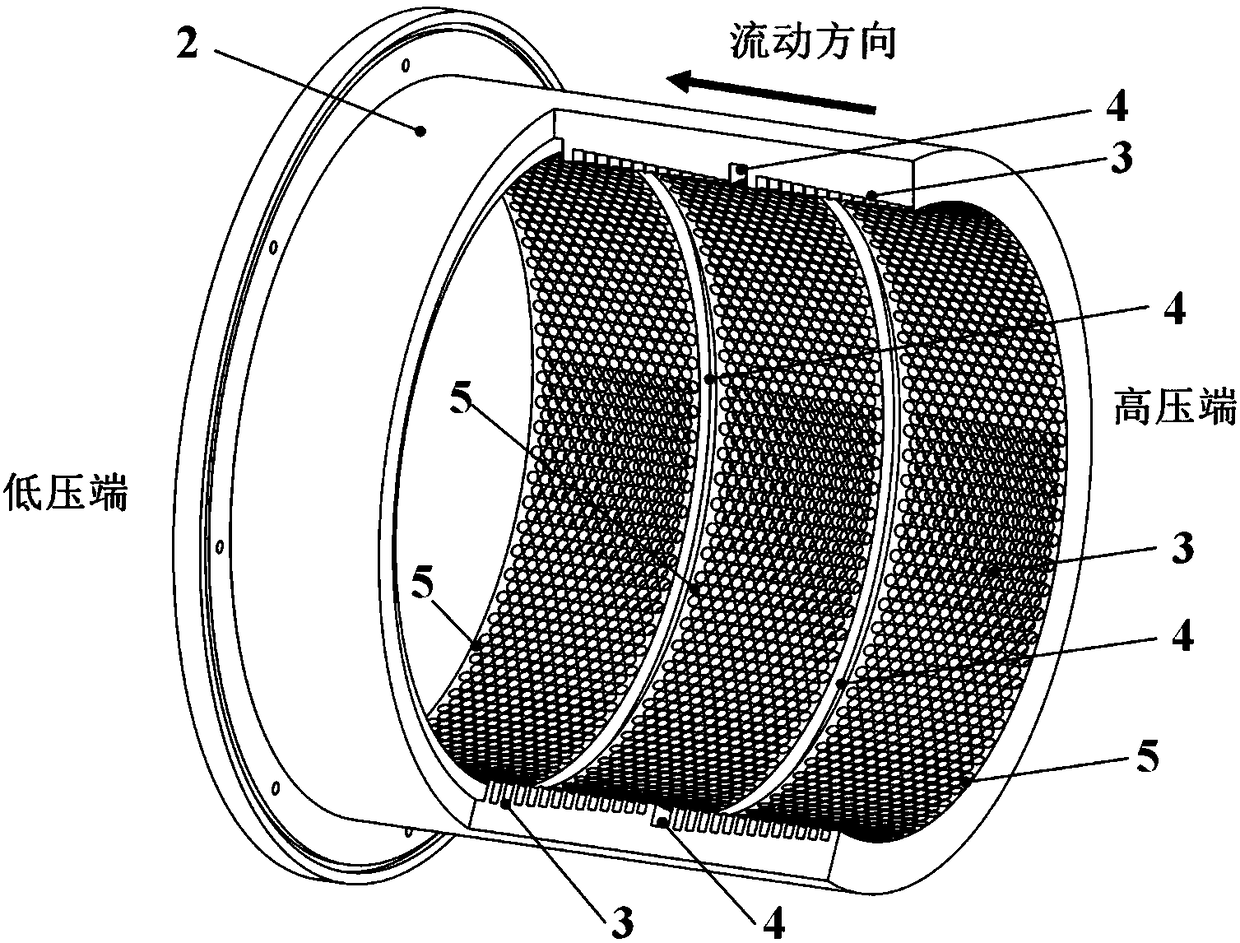
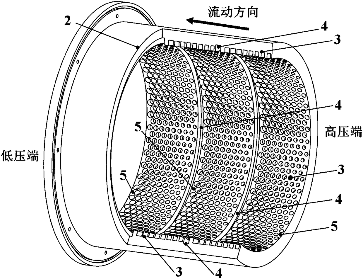
[0044] see Figure 2a to Figure 2d , On the inner surface 5 of the sealing stator part of the rotary sealing structure of the present invention, a hole-type sealing cavity structure 3 and an ann...


PUM


Abstract

The invention discloses a nonuniform controllable cavity rotary sealing structure. The sealing structure is a sealing stator used for being mounted on a rotating part in a sleeving mode and comprisesa hole-type sealing cavity and an annular pressure stabilizing cavity both formed in the inner surface of the sealing stator. The processing section of the hole-type sealing cavity can be circular, oval or hexagonal, and the annular pressure stabilizing cavity is through in the circumferential direction. The hole diameter and hole depth of the hole-type sealing cavity are changed according to a set rule in the axial direction and the circumferential direction, and the changing rule can be a linear type, a quadratic curve type, a cosine curve type and a B-spline curve type. The inner surface ofthe sealing stator is divided into a plurality of independent sealing sections by the annular pressure stabilizing cavity, and the sealing sections can independently regulate and control the hole diameter and the hole depth of the hole-type sealing cavity. Fine regulation and control over the magnitude and symbols of sealing power characterization factors (rigidity and damping) can be realized, the sealing power characterization is improved, and the impeller mechanical shafting stability is improved.

Description

technical field [0001] The present invention relates to a rotary sealing structure, in particular to a non-uniform controllable chamber used in the shafting of a turbomachinery, which has the functions of controlling leakage, suppressing vibration and increasing stability, and meets the requirements of refined controllable adjustment of stiffness and damping of the shafting of a modern turbomachinery Rotary seal structure. Background technique [0002] The working fluid leakage between the rotating part and the stationary part in the turbomachinery is one of the main sources of loss. The rotating seal can control the leakage flow from the high-pressure area to the low-pressure area through the dynamic and static gap, effectively reducing the amount of leakage and the impact of the leakage flow. The effect of the mainstream has a significant effect on the operating efficiency of the turbomachinery. While the rotary seal controls the leakage flow of the working fluid, due to ...

Claims


Application Information

Patent Timeline
IPC IPC(8): F04D29/16F01D11/00
CPCF01D11/003F04D29/162
Inventor 李志刚李军
Owner XI AN JIAOTONG UNIV
Learn More