Vibrating mirror-based spiral scanning laser projection method and system

A scanning laser and helical line technology, applied in the direction of optics, optical components, instruments, etc., can solve the problems of low vibration resistance, low projection resolution, complex algorithm, etc., to achieve small driving force, simple projection algorithm, and uniform projection screen Effect

Active Publication Date: 2018-08-14
XI AN ZHISENSOR TECH CO LTD
View PDF4 Cites 6 Cited by
  • Summary
  • Abstract
  • Description
  • Claims
  • Application Information

AI Technical Summary

Problems solved by technology

[0004] The purpose of the present invention is to provide a helical line scanning laser projection method based on the vibrating mirror, which makes the vibrating mirror resonate around two axes, and the scanning trajectory is a helical scanning, which solves the problem that the current laser projection display based on the MEMS vibrating mirror is scanned by Lissajous. In the raster scanning method, there are problems such as complex algorithm, low projection resolution, low resonant frequency of the galvanometer, and low anti-vibration ability.

Method used


Image

  • Vibrating mirror-based spiral scanning laser projection method and system
  • Vibrating mirror-based spiral scanning laser projection method and system
  • Vibrating mirror-based spiral scanning laser projection method and system

Examples


Embodiment 1

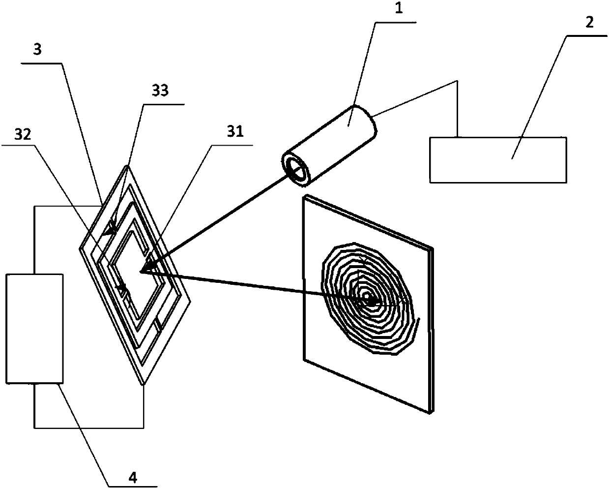
[0063] from figure 1 It can be seen that the projection system of this embodiment mainly includes: a laser light source 1 , a laser light source control module 2 , a vibrating mirror 3 and a vibrating mirror control module 4 . The laser light source 1 can be incident on the reflective surface 31 of the galvanometer, and the laser beam reflected from the reflective surface 31 of the galvanometer is scanned to obtain a projected image.

[0064] Among them, the laser light source 1 provides a light source for the projection system. The laser light source can be a monochromatic laser or a multi-band fusion laser; the laser light source control module 2 can realize the adjustment of the laser light source, and complete the adjustment of the laser light source brightness from zero to maximum in real time. value adjustment.

[0065] Among them, the dual-axis vibrating mirror 3 has modes of twisting around two orthogonal axes (x-axis 32 and y-axis 33 ) at the same frequency. When the...

Embodiment 2

[0089] from Figure 10 It can be seen that the laser projection system in this embodiment includes: a laser light source 1 , a laser light source control module 2 , a first single-axis vibrating mirror 5 , a second single-axis vibrating mirror 6 and a vibrating mirror control module 4 . Wherein the laser light source 1 can be incident on the first uniaxial galvanometer reflective surface of the first uniaxial galvanometer 5, then reflected to the second uniaxial galvanometer reflective surface, and emitted from the second uniaxial galvanometer 6 reflective surface A laser line projects a projected image.

[0090] Among them, the laser light source 1 provides a light source for the projection system. The laser light source can be a monochromatic laser or a multi-band fusion laser. The laser light source control module 2 can realize the adjustment of the laser light source and complete the brightness of the laser light source from zero to the maximum in real time. adjustment. ...

Embodiment 3

[0110] from figure 1 It can be seen that the projection system of this embodiment mainly includes: a laser light source 1 , a laser light source control module 2 , a vibrating mirror 3 and a vibrating mirror control module 4 . The laser light source 1 can be incident on the reflective surface 31 of the galvanometer, and the laser beam reflected from the reflective surface 31 of the galvanometer is scanned to obtain a projected image.

[0111] Among them, the laser light source 1 provides a light source for the projection system. The laser light source can be a monochromatic laser or a multi-band fusion laser; the laser light source control module 2 can realize the adjustment of the laser light source, and complete the adjustment of the laser light source brightness from zero to maximum in real time. value adjustment.

[0112] Among them, the dual-axis vibrating mirror 3 has modes of twisting around two orthogonal axes (x-axis 32 and y-axis 33 ) at the same frequency. When the...


PUM


Abstract

The invention belongs to the field of laser projection display and relates to a vibrating mirror-based laser projection display method and specifically relates to a vibrating mirror-based spiral scanning laser projection method and system. A vibrating mirror is enabled to perform resonance oscillation around two axes, a scanning trajectory is spirally scanned, and the scanning trajectory is used to realize projection. The vibrating mirror-based spiral scanning laser projection method and system can be used for solving problems of complex algorithms, low projection resolution, excessively low resonant frequency of the vibrating mirror, low vibration resistance vibration resistance and the like of conventional MEMS vibrating mirror-based laser projection display which is performed via a Lissajous Scanning and grating scanning method.

Description

technical field [0001] The invention belongs to the field of laser projection display, and relates to a laser projection display method based on a vibrating mirror, in particular to a helical scanning laser projection method and system based on a vibrating mirror. Background technique [0002] In recent years, with the development of virtual reality (VR, Virtual Reality) and augmented reality (AR, Augmented Reality) technology, its application has entered various fields such as aviation, industry, medicine, education, entertainment, etc., and major manufacturers at home and abroad have launched A variety of VR and AR projection devices, among which the head-mounted display-based smart glasses attract the most attention. The main directions of projection display are: based on LCOS, OLED and other display imaging displays, such as Google Glass, Oculus Rift, Sony Project Morpheus, Samsung Gear VR , HTC Vive, etc.; based on DLP projection, such as Microsoft Hololens; the display...

Claims


Application Information

Patent Timeline
Patent Type & Authority Applications(China)
IPC IPC(8): G02B26/08G02B26/10G03B21/00G03B21/20
CPCG02B26/0833G02B26/101G03B21/008G03B21/2033
Inventor 夏长锋宋秀敏乔大勇何伟
Owner XI AN ZHISENSOR TECH CO LTD
Why Eureka
Try Eureka