

Fingerprint identification structure and display device
A fingerprint recognition and fingerprint technology, which is applied in character and pattern recognition, acquisition/organization of fingerprints/palmprints, print image collection, etc., can solve the problems of low accuracy of fingerprint recognition, achieve the effect of avoiding mutual interference and improving accuracy
- Summary
- Abstract
- Description
- Claims
- Application Information
AI Technical Summary
Problems solved by technology
Method used
Image

Examples
Embodiment approach 1
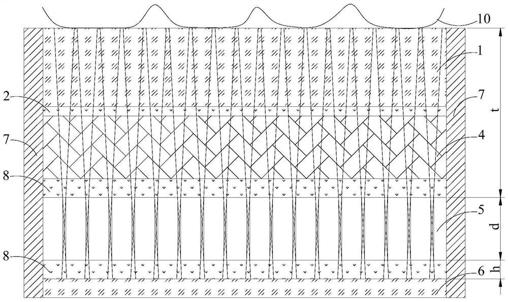
[0046] refer to figure 1 A structural schematic diagram of an example implementation of the shown fingerprint recognition structure.
[0047] The fingerprint identification structure may include a photodetector 6, a filter device 5, a display device 4, etc. arranged in sequence from bottom to top.
[0048] In this exemplary embodiment, the photodetector 6 may be touch sensing glass (sensor glass), that is, the photodetector 6 is disposed on a glass substrate. The photodetector 6 and the filter element 5 can be bonded by optical glue 8 .
[0049] In this exemplary embodiment, the display device 4 can be used as a light source, that is, the fingerprint 10 can reflect the light emitted by the display device 4 . The optical filter device 5 and the display device 4 can be bonded by optical glue 8 . The display device 4 may be a self-luminous display, for example, the display device 4 may be an organic light emitting diode display, such as a micro light emitting diode display (Mi...
Embodiment approach 2
[0066] Figure 5 It is a structural schematic diagram of another exemplary embodiment of the fingerprint identification structure of the present invention.
[0067] There are two main differences between this exemplary embodiment and the first exemplary embodiment: first, the display device 4 is not used as a light source, but is additionally provided with a special light source; second, the function of the light transmission plate 1 is different.
[0068] In this exemplary embodiment, the light source is disposed on a side of the light transmission plate 1 intersecting the light incident surface. The light incident surface can be the upper surface of the light transmission plate 1, and the light exit surface can be the lower surface of the light transmission plate 1, then, the side of the light transmission plate 1 intersecting the light incident surface can be the left side of the light transmission plate 1 , right side, front side or rear side. Therefore, the light source...
Embodiment approach 3
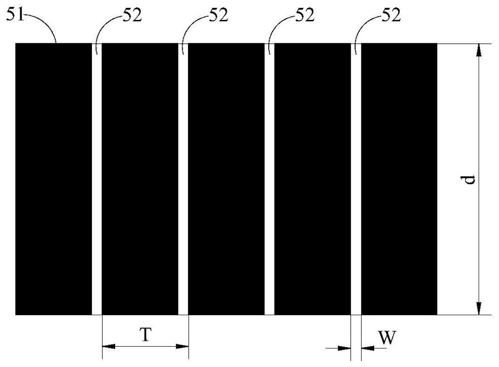
[0075] Figure 6 It is a structural schematic diagram of another exemplary embodiment of the fingerprint recognition structure of the present invention.
[0076] The main difference between this exemplary embodiment and the second exemplary embodiment is that: the optical adhesive layer disposed between the optical transmission board 1 and the optical filter device 5 is frame adhesive.
[0077] In this exemplary embodiment, the frame adhesive only bonds the periphery of the optical transmission plate 1 and the optical filter device 5, and does not adhere to the middle part. The frame adhesive has a certain thickness, so that the optical transmission plate 1 and the optical filter device 5 to form an air gap. The refractive index of air is smaller than that of the light transmission plate 1 , as long as the incident angle of the light is larger than the critical angle, the light will be totally reflected in the light transmission plate 1 . All the light incident on the side o...
PUM
| Property | Measurement | Unit |
|---|---|---|
| refractive index | aaaaa | aaaaa |
| refractive index | aaaaa | aaaaa |
| refractive index | aaaaa | aaaaa |
Abstract
Description
Claims
Application Information