Optical fiber link detection system and method based on linear frequency modulation signal

A chirp signal and optical fiber link technology, applied in transmission systems, electromagnetic wave transmission systems, electrical components, etc., can solve the problems of reducing distance resolution and time-consuming

Inactive Publication Date: 2018-08-14
WUHAN POST & TELECOMM RES INST CO LTD
View PDF3 Cites 2 Cited by
  • Summary
  • Abstract
  • Description
  • Claims
  • Application Information

AI Technical Summary

Problems solved by technology

Oversampling increases the dynamic range of the measurement, but takes more time
Due to the limited power of the laser, to increase the energy of the incident signal, the only way to increase the pulse width of the transmitted signal is to reduce the distance resolution.

Method used


Image

  • Optical fiber link detection system and method based on linear frequency modulation signal
  • Optical fiber link detection system and method based on linear frequency modulation signal
  • Optical fiber link detection system and method based on linear frequency modulation signal

Examples


Embodiment Construction

[0036] The present invention will be described in further detail below in conjunction with the accompanying drawings and embodiments.

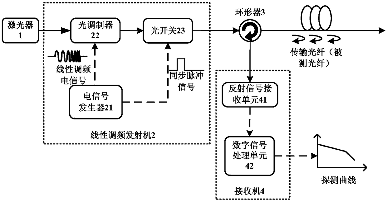
[0037] Such as figure 1 As shown, the optical fiber link detection system based on the chirp signal of the present invention includes a laser 1 , a chirp transmitter 2 , a circulator 3 and a receiver 4 . Among them, the laser 1 is used to send out continuous optical signals. The chirp transmitter 2 is used to generate a repetitive pulse signal including a chirp optical signal as a detection optical signal. The circulator 3 is used to input the detection optical signal into the optical fiber under test (ie, the transmission optical fiber), and receive the backscatter signal from the optical fiber under test. The receiver 4 is used to extract the characteristics of the optical fiber under test carried in the backscattering signal, and output the detection signal curve track as the output detection result. Preferably, the circulator 3 may be a...


PUM


Abstract

An optical fiber link detection system based on a linear frequency modulation signal relates to the field of optical fiber communication. The system comprises a laser, a linear frequency modulation transmitter, a circulator and a receiver, wherein the laser emits a continuous optical signal; the linear frequency modulation transmitter generates a repetitive pulse signal including a linear frequency modulation signal to act as a detection optical signal; the circulator inputs the detection optical signal into an optical fiber under test and receives a backscattered signal from the optical fiberunder test; and the receiver extracts the features of the optical fiber under test carried in the backscattered signal and outputs a curve track of the detection signal. By adopting the scheme of theinvention, the dynamic range of measurement and the range resolution can be improved under the premise of the same time.

Description

technical field [0001] The invention relates to the field of optical fiber communication, in particular to an optical fiber link detection system and method based on chirp signals. Background technique [0002] Optical Time Domain Reflectometry (OTDR) technology is based on the principle of backscattering and reflection of light. It uses the backscattered light generated when light is transmitted in the optical fiber to obtain attenuation information. Understand the loss distribution of the fiber along the length, etc. Due to the uneven density of the fiber material, the uneven doping composition and the defects of the fiber itself, when the light pulse is transmitted in the fiber, it will be scattered due to the nature of the fiber itself, connectors, joints, bending or other similar events. reflection. A part of the scattered and reflected light will return to the optical time domain reflectometer (Optical Time Domain Reflectometer, OTDR), and the returned useful informa...

Claims


Application Information

Patent Timeline
Patent Type & Authority Applications(China)
IPC IPC(8): H04B10/071H04B10/516
CPCH04B10/071H04B10/516
Inventor 李蔚余少华
Owner WUHAN POST & TELECOMM RES INST CO LTD
Why Eureka
Try Eureka