Smoke and dust removal device for rural garbage treatment

A technology of garbage disposal and dust removal device, which is applied in the direction of combination device, dispersed particle separation, chemical instruments and methods, etc., can solve the problems of inability to mix cooling liquid, low cooling efficiency, greenhouse effect, etc., and achieves easy cooling, desulfurization and dust removal, The effect of preventing clogging

Active Publication Date: 2018-08-17
章雪霞
View PDF5 Cites 1 Cited by
  • Summary
  • Abstract
  • Description
  • Claims
  • Application Information

AI Technical Summary

Problems solved by technology

However, the waste incinerator will produce a large amount of flue gas during the incineration process. The flue gas contains a large amount of dust and waste heat. Direct discharge into the atmosphere will cause local acid rain, greenhouse effect, etc., causing serious pollution to the atmospheric environment.
The flue gas dedusting and heat removal devices in the prior art have the following problems in use: 1. After the dust in the flue gas is dedusted by the dedusting device, the filter screen inside the dedusting device is easily blocked, and frequent flushing or back blowing for dedusting is required ; 2. In the prior art, after the flue gas containing dust and waste heat enters the inside of the cooling tower, it cannot be mixed with the cooling liquid inside the cooling tower quickly and efficiently, and the cooling efficiency is low

Method used


Image

  • Smoke and dust removal device for rural garbage treatment
  • Smoke and dust removal device for rural garbage treatment
  • Smoke and dust removal device for rural garbage treatment

Examples


specific Embodiment approach 1

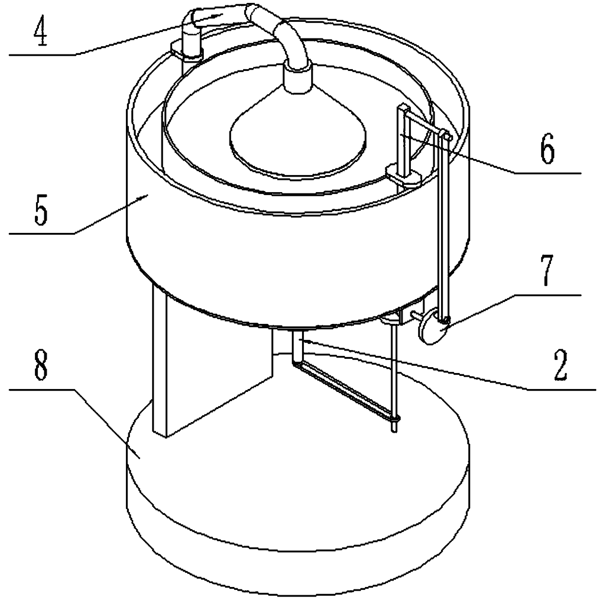
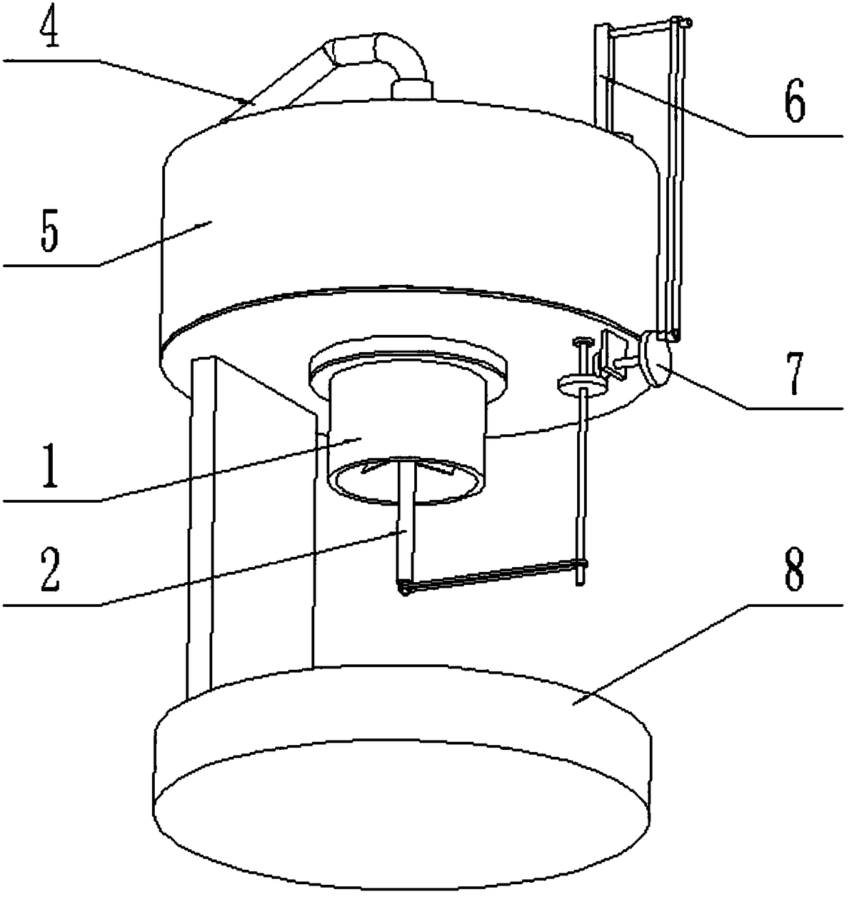
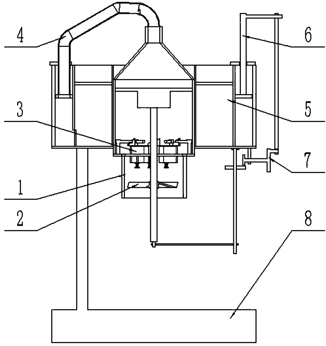
[0032] like Figure 1-13 As shown, the smoke and dust removal device for rural garbage treatment includes a dust collection box assembly 1, a dust collection impeller assembly 2, a rotary filter device 3, a dust delivery pipe assembly 4, a dust removal water tank assembly 5, a lift transformer plate assembly 6, and a transmission wheel Assembly 7 and supporting base 8, the dust collection box assembly 1 includes a dust suction pipe 1-1, a dust blocking pipe 1-2, a fixed seat plate 1-3, six blocking dust rods 1-4 and a pipe connection ring 1 -5; the upper end of the dust suction pipe 1-1 is fixedly connected to the lower end of the pipe connection ring 1-5, and the upper end of the pipe connection ring 1-5 is fixedly connected to the dust blocking pipe 1-2; the pipe connection ring 1-5 The top surface of the top surface is evenly arranged with six blocking dust rods 1-4; the fixed seat plate 1-3 is fixedly connected to the inner upper end of the dust blocking pipe 1-2;

[0033] ...

specific Embodiment approach 2

[0035] like Figure 1-13 As shown, the rotary filter device 3 includes a rotary dust-blocking plate 3-1, a stainless steel dust-removing basket 3-2, a sloping plate 3-3 and a spring seat assembly 3-4; the rotary dust-blocking plate 3-1 is fixedly connected On the rotating shaft 2-2, the outer wall of the rotating dust blocking plate 3-1 is tangent to the upper end of the inner wall of the dust suction pipe 1-1; the rotating dust blocking plate 3-1 is provided with six slotted openings, six The inboards of each slot-shaped opening are respectively slidingly fitted to connect a stainless steel dust removal net basket 3-2, and the tops of six stainless steel dust removal net baskets 3-2 are respectively fixedly connected with a slant plate 3-3, and the tops of the six stainless steel dust removal net baskets 3-2 are fixedly connected. Each bottom end is fixedly connected to a spring seat assembly 3-4, and the upper end of the spring seat assembly 3-4 is fixedly connected to the b...

specific Embodiment approach 3

[0038] like Figure 1-13 As shown, the dust delivery pipe assembly 4 includes a dust delivery bucket 4-1, a telescopic hose 4-2 and a lift slide tube 4-3; the lower end of the dust delivery bucket 4-1 is fixedly connected and communicated with the dust blocking pipe 1 -2; the upper end of the dust hopper 4-1 is fixedly connected to one end of the flexible hose 4-2, and the other end of the flexible hose 4-2 is fixedly connected to the lifting slide pipe 4-3; the lifting slide The lower end of the pipe 4-3 is fixedly connected to the lifting transformer plate assembly 6. When the dust conveying pipe assembly 4 is in use, the flue gas enters the interior of the dust conveying hopper 4-1 through the dust blocking pipe 1-2, and enters the telescopic hose 4-2 and the lifting slide through the dust conveying hopper 4-1. The inner side of the pipe 4-3 finally enters the inside of the dust removal water tank assembly 5 through the lifting slide pipe 4-3.


PUM


Abstract

The invention relates to a dust removal device, in particular to a smoke and dust removal device for rural garbage treatment. The smoke and dust removal device for rural garbage treatment comprises adust suction tank component, a dust suction impeller component, a rotary filter device, a dust conveying pipe component, a dust removal water tank component, a lifting variable-pressure plate component, a transmission wheel component and a supporting base; the dust suction tank component comprises a dust suction pipe, a dust blocking pipe, a fixed seat plate, six falling dust retaining rods and apipe connection ring; the upper end of the dust suction pipe is fixedly connected to the lower end of the pipe connection ring; the upper end of the pipe connection ring is fixedly connected with thedust blocking pipe; the six falling dust retaining rods are uniformly arranged on the top surface of the pipe connection ring in a surrounding manner; and the fixed seat plate is fixedly connected tothe upper end of the interior of the dust blocking pipe. By adopting the smoke and dust removal device for rural garbage treatment, when the interior rotary filter device filters dusts in flue gas, falling dust retaining treatment can be continuously performed through the falling dust retaining rods, and a stainless steel dust removal net basket can be effectively prevented from being blocked.

Description

technical field [0001] The invention relates to a dust removal device, in particular to a smoke and dust removal device for rural garbage treatment. Background technique [0002] At present, the most common method of garbage disposal is garbage incineration, using garbage incinerators to incinerate municipal solid waste, and the heat generated can be used to generate electricity. However, the waste incinerator will produce a large amount of flue gas during the incineration process. The flue gas contains a large amount of dust and waste heat. Direct discharge into the atmosphere will cause local acid rain, greenhouse effect, etc., and cause serious pollution to the atmospheric environment. The flue gas dedusting and heat removal devices in the prior art have the following problems in use: 1. After the dust in the flue gas is dedusted by the dedusting device, the filter screen inside the dedusting device is easily blocked, and frequent flushing or back blowing for dedusting is...

Claims


Application Information

Patent Timeline
Patent Type & Authority Applications(China)
IPC IPC(8): B01D50/00
CPCB01D50/60
Inventor 章雪霞
Owner 章雪霞
Why Eureka
Try Eureka