Sheet metal pulse current auxiliary micro bending forming device and method

A technology of pulse current and metal sheet, applied in the direction of metal processing equipment, forming tools, manufacturing tools, etc., can solve the problems of difficult workpiece clamping, difficult to control forming, poor positioning accuracy, etc., to achieve the solution of difficult clamping, cost reduction, Solve the effect of poor mold positioning accuracy

Active Publication Date: 2018-08-17
HARBIN INST OF TECH
View PDF6 Cites 18 Cited by
  • Summary
  • Abstract
  • Description
  • Claims
  • Application Information

AI Technical Summary

Problems solved by technology

[0003] The present invention aims to solve the problem of difficult forming caused by workpiece clamping difficulty, poor positioning accuracy, large amount of springback and difficult control in the existing micro-bending forming process, and further provides a pulse-current assisted micro-bending forming device for metal sheets and method

Method used


Image

  • Sheet metal pulse current auxiliary micro bending forming device and method
  • Sheet metal pulse current auxiliary micro bending forming device and method
  • Sheet metal pulse current auxiliary micro bending forming device and method

Examples


specific Embodiment approach 1

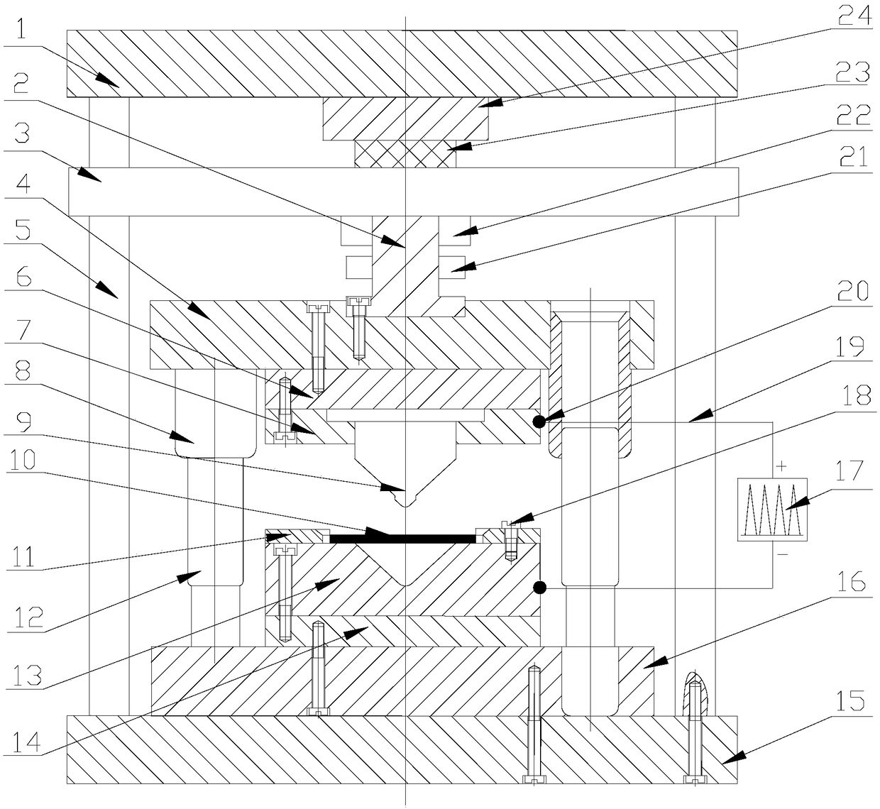
[0034] Specific implementation mode one: combine Figure 1 to Figure 4 Describe this embodiment. A pulse current assisted micro-bending forming device for a thin metal plate in this embodiment includes a mold assembly, a loading device, a pulse power supply system, and a control system. The mold assembly is installed in the loading device, and the pulse power supply system is connected to the mold assembly. The pulse is provided to the mold assembly, the loading device and the pulse power supply system are connected with the control system, and the mold assembly, the loading device and the pulse power supply system are automatically controlled through the control system.

[0035] Current-assisted forming refers to a processing technology that applies continuous current or pulse current to the blank while plastically deforming. Current research shows that applying current during the micro-forming process can reduce the influence of the scale effect, and the current for micro-be...

specific Embodiment approach 2

[0036] Specific implementation mode two: combination figure 1 Describe this embodiment, the mold assembly of this embodiment comprises upper template 4, upper insulating plate 6, copper electrode 7, punch 9, die 13, positioning plate 11, lower insulating plate 14, lower template 16, guide sleeve 8 and Guide column 12; the upper center of the upper template 4 is opened and a mold handle 2 is installed, and the upper and lower ends of the mold handle 2 are respectively connected with the press slider 3 of the loading device and the upper template 4; the upper insulating plate 6 is installed on the upper The lower end of the template 4, the punch 9 is installed on the lower end of the upper insulating plate 6 through the copper electrode 7; the lower template 16 is installed directly below the upper template 4, and the guide sleeve 8 and the guide post 12 are passed between the lower template 16 and the upper template 4 Connection, the lower insulating plate 14 is installed on th...

specific Embodiment approach 3

[0037] Specific implementation mode three: combination figure 1Describe this embodiment, the loading device of this embodiment includes a press upper plate 1, a press slider 3, a press guide rail 5, a press platform 15, a pressure sensor 22, a displacement sensor 21, a piezoelectric ceramic 23 and a booster transmission device 24. The upper plate 1 of the press, the slider 3 of the press and the platform 15 of the press are connected sequentially through the guide rail 5 of the press from top to bottom, and the mold assembly is installed between the slider 3 of the press and the platform 15 of the press; Between the machine upper plate 1 and the press slider 3, a booster transmission device 24 and a piezoelectric ceramic 23 are installed sequentially from top to bottom, the pressure sensor 22 is installed on the pressure collection point of the press slider 3, and the displacement sensor 21 is installed on the On the displacement acquisition point of die handle 2. Such settin...


PUM

PropertyMeasurementUnit
thicknessaaaaaaaaaa

Abstract

The invention discloses a sheet metal pulse current auxiliary micro bending forming device and method, and relates to a micro bending forming device and method. The sheet metal pulse current auxiliarymicro bending forming device and method are used for solving the problems that in an existing micro bending forming process, forming is difficult because a workpiece is difficult to clamp, the accuracy of positioning is low, the amount of springback is large, control is difficult to carry out, and so on. The sheet metal pulse current auxiliary micro bending forming device comprises a die assembly, a loading device, a pulse power source system and a control system. The die assembly is installed in the loading device. The pulse power source system is connected with the die assembly and providespulses for the die assembly. Both the loading device and the pulse power source system are connected with the control system. The die assembly, the loading device and the pulse power source system are automatically controlled through the control system. The micro bending forming method comprises the steps of firstly, installing a micro workpiece; secondly, enabling a male die to make contact withthe micro workpiece; thirdly, loading the micro workpiece; and fourthly, completing the micro bending forming of the micro workpiece. The micro bending forming device and method are suitable for carrying out micro bending forming on the materials which cannot be easily formed or cannot be formed with a common micro bending method.

Description

technical field [0001] The invention relates to a micro-bending forming device and method, in particular to a pulse current-assisted micro-bending forming device and a forming method; it belongs to the technical field of mechanical manufacturing and plastic micro-forming. Background technique [0002] With the rapid development and gradual practical application of Micro-Electro-Mechanical Systems (MEMS) technology, the demand for micro-parts is increasing, especially for micro-sheet connectors, spring accessories and micro-clamps in the field of microelectronics. Clamps, etc., whose part size or feature size is on the order of submillimeter or micron, belong to the category of mesoscopic scale. During the micro-bending forming process, there are obvious scale effects of mechanical properties and springback scale effects, which seriously affect the micro-bending forming process. piece geometric accuracy. At the same time, due to the existence of the scale effect, it is diffi...

Claims


Application Information

Patent Timeline
Patent Type & Authority Applications(China)
IPC IPC(8): B21D37/10B21D37/16B21D5/06
CPCB21D5/06B21D37/10B21D37/16
Inventor 郭斌徐杰单德彬包建兴
Owner HARBIN INST OF TECH
Why Eureka
Try Eureka