Hub flexible casting riser machining system based on machine vision

A machine vision and wheel hub flexibility technology, applied in the field of automated machinery, can solve the problems of reducing machine tool processing efficiency, increasing manual workload, lack of adaptability of different types of wheel hubs, etc., to achieve compact structure, fast indexing speed, high reliability and performance. Effect

Pending Publication Date: 2018-08-17
XIANGNONG INTELLIGENT TECH CO LTD
View PDF0 Cites 1 Cited by
  • Summary
  • Abstract
  • Description
  • Claims
  • Application Information

AI Technical Summary

Problems solved by technology

[0003] The first process of rough machining of motorcycle aluminum alloy wheel blanks is to cut the riser produced by casting, which is convenient for the subsequent finishing of the wheel hub. The current processing technology is to cut the riser with a saw blade, and the cutting reference plane is based on the bottom of the wheel hub. The surface is the reference plane, and the saw blade cuts the wheel riser along the cutting surface of the wheel hub. The motorcycle aluminum alloy wheel hub models are generally different in shape and size, so the processing equipment needs to have high flexibility to be compatible with different types of hubs; The diameter of the aluminum alloy wheel of the car is distributed from 10 inches to 19 inches. When cutting the hub riser, the tooling fixture of the equipment needs to be compatible with wheels of different sizes from 10 to 19 inches; The distance is different, and the distance parameters between the saw blade and the base surface are different during processing, so the tool parameters must be manually switched when processing different types of hubs; in summary, the existing processing equipment lacks adaptability to different types of hubs, which increases the Manual workload reduces the efficiency of machine tool processing

Method used


Image

  • Hub flexible casting riser machining system based on machine vision
  • Hub flexible casting riser machining system based on machine vision
  • Hub flexible casting riser machining system based on machine vision

Examples


Embodiment Construction

[0018] The following will clearly and completely describe the technical solutions in the embodiments of the present invention. Obviously, the described embodiments are only some of the embodiments of the present invention, rather than all the embodiments. Based on the embodiments of the present invention, all other embodiments obtained by persons of ordinary skill in the art without making creative efforts belong to the protection scope of the present invention.

[0019] see Figure 1 to Figure 4 , the embodiment of the present invention includes:

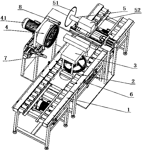
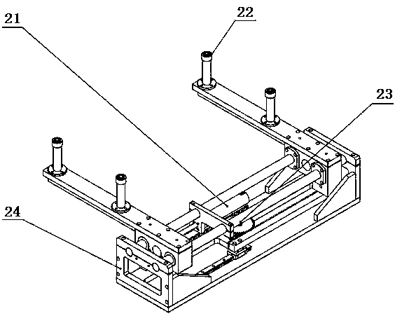
[0020] A wheel hub flexible casting riser processing system based on machine vision, including: a conveyor line 1, a centering mechanism for positioning the wheel hub 2, a loading and unloading mechanism for moving and turning the wheel hub 3, and a saw blade for determining the processing The machine vision positioning device for the surface, the fixture 4 and the cutting system 5 for cutting the riser of the hub.

[0021] Conve...


PUM

PropertyMeasurementUnit
diameteraaaaaaaaaa

Abstract

The invention discloses a hub flexible casting riser machining system based on machine vision. The hub flexible casting riser machining system comprises a conveying line, a centering mechanism for positioning a hub, a feeding and discharging mechanism for moving and overturning the hub, a machine vision positioning device for determining a machining surface of a saw blade, a tool clamp and a cutting system for cutting a hub riser. According to the hub flexible casting riser machining system based on machine vision, in this way, clamping of different models of hubs is achieved by adopting a step-type hydraulic clamp, the cutting surface of the saw blade is determined through the machine vision positioning device, the hub flexible casting riser machining system has the advantages that reliable performance is high, positioning is accurate, the structure is compact, the transposition speed is high, the adaptability is high, and the efficiency is high, and meanwhile, the hub flexible casting riser machining system has wide market prospects in application and popularization of hub machining.

Description

technical field [0001] The invention relates to the field of automated machinery, in particular to a machine vision-based processing system for flexible casting risers of hubs. Background technique [0002] The casting of aluminum alloy wheels for motorcycles in foreign countries emerged in the 1960s. At present, my country has become a major producer of aluminum alloy wheels for motorcycles. The casting methods used are mainly metal-type gravity casting and vacuum high-pressure casting. It is widely used because of low technical requirements and low investment; when metal mold gravity casting is poured, the fluid relies on gravity to flow and fill the mold. Since there is no external pressure, in order to obtain dense castings, it is often necessary to use the riser to feed the shrinkage, so , The aluminum alloy wheel blanks formed by metal gravity casting have heavier risers that need to be processed. [0003] The first process of rough machining of motorcycle aluminum allo...

Claims


Application Information

Patent Timeline
Patent Type & Authority Applications(China)
IPC IPC(8): B22D31/00
CPCB22D31/00
Inventor 施晓明
Owner XIANGNONG INTELLIGENT TECH CO LTD
Why Eureka
Try Eureka