Numerical control grinding machine pneumatic clamp for gear grinding

A CNC grinding machine and pneumatic fixture technology, which is applied to components with teeth, gear teeth manufacturing devices, belts/chains/gears, etc., can solve the problems that can not really meet the requirements of automatic production, low safety factor, time-consuming and labor-intensive, etc. , to achieve stability and high precision, improve the safety factor, and ensure the effect of circumferential stability and precision

Pending Publication Date: 2018-08-17
HEFEI CHANGYUAN HYDRAULICS
View PDF0 Cites 5 Cited by
  • Summary
  • Abstract
  • Description
  • Claims
  • Application Information

AI Technical Summary

Problems solved by technology

[0004] As a gear processing industry, the traditional gear grinding method is to use the chicken heart chuck to clamp the workpiece. When the operator is grinding the gear, first clamp the chicken heart chuck to the end of the gear shaft head, and then put it into the fixed thimble of the ordinary grinding machine. Move the movable thimble on one side and the other side and release it to complete the clamping; the whole process is time-consuming and labor-intensive, and the safety factor is not high
[0005] The modern gear grinding method is to use a CNC grinding machine. The movable thimble is controlled by hydraulic pressure, and the fixed thimble at the other end is equipped with a centrifugal spring clamping fixture; You only need to pull down the spring to open the gap to put the gear in; but the clamping force is small, which cannot really meet the requirements of automatic production

Method used


Image

  • Numerical control grinding machine pneumatic clamp for gear grinding
  • Numerical control grinding machine pneumatic clamp for gear grinding
  • Numerical control grinding machine pneumatic clamp for gear grinding

Examples


Embodiment Construction

[0035] refer to Figures 1 to 10 As shown, the structural features of the pneumatic clamp for CNC grinding machine used for gear grinding are described in detail as follows:

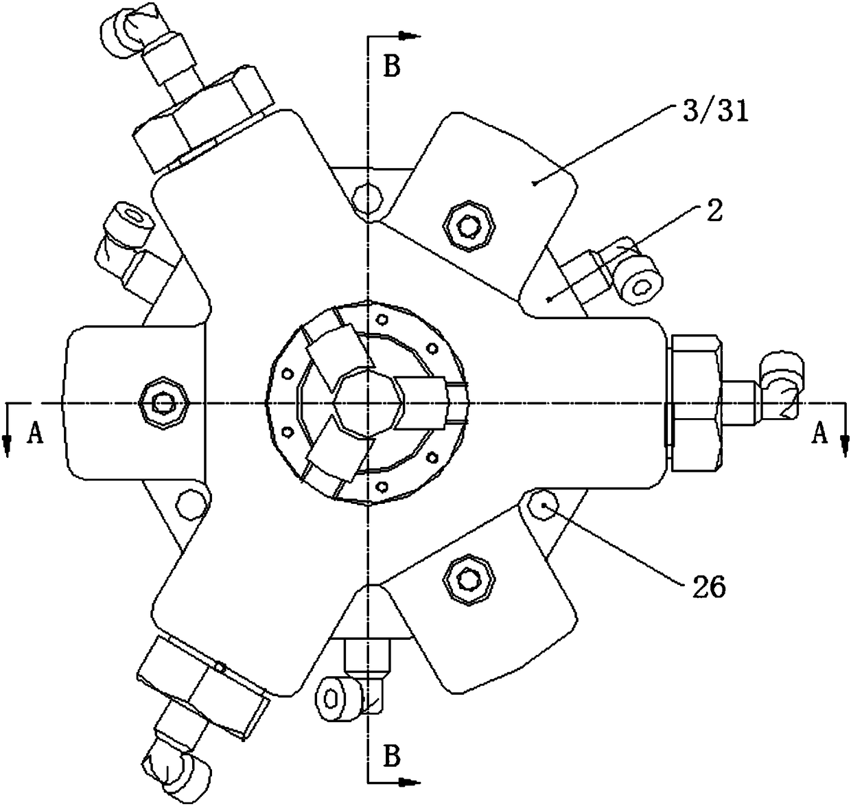
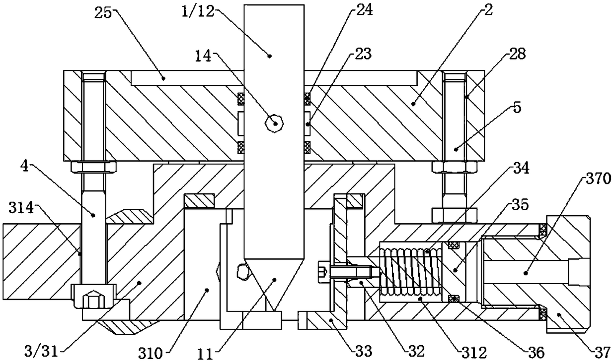
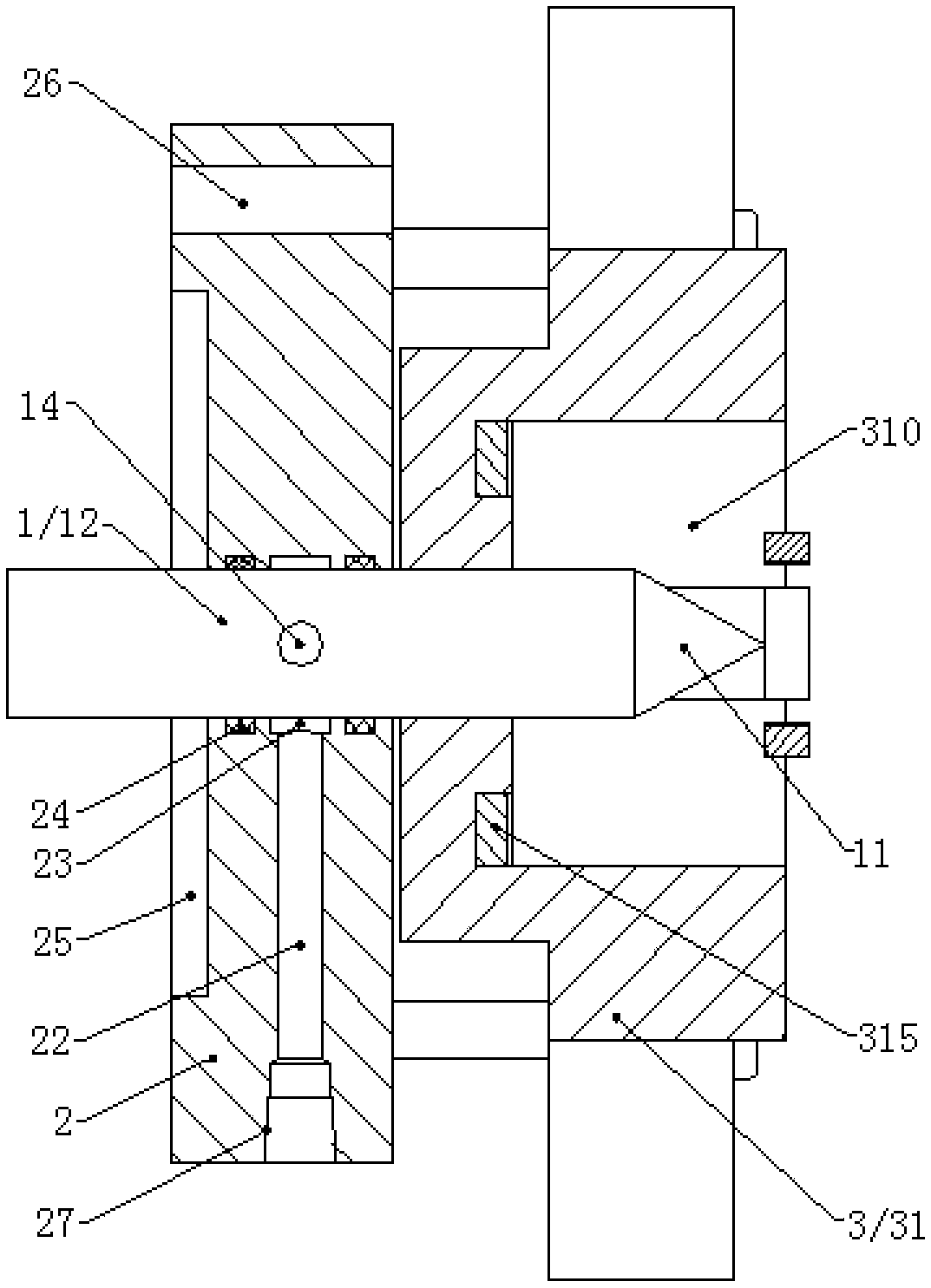
[0036] A pneumatic fixture for a CNC grinding machine used for gear grinding, which includes a thimble 1; the fixture also includes a chassis 2 and a cylinder 3, one end of the chassis 2 is fixed on the bed base, and the cylinder 3 is fixed on the chassis 2 The other end, and the cylinder 3 includes a clamping cavity 310; the thimble 1 is set through the chassis 2, wherein, one end of the thimble 1 is fixedly connected to the bed base, and the tip 11 of the other end of the thimble 1 is placed on the cylinder 3 In the clamping chamber 310.

[0037] When the pneumatic fixture of the CNC grinding machine is used for grinding gears, the gears are placed in the clamping chamber 310 of the cylinder 3, and the circumferential stability of the gear clamping is ensured by the cylinder 3; since one end of the th...


PUM


Abstract

The invention discloses a numerical control grinding machine pneumatic clamp for gear grinding. The numerical control grinding machine pneumatic clamp comprises a centre. The clamp further comprises abase plate and an air cylinder. One end of the base plate is fixedly arranged on a lathe bed base, and the air cylinder is fixedly arranged at the other end of the base plate and comprises a clampingcavity. The centre penetrates the base plate. One end of the centre is fixedly connected with the lathe bed base, and a tip at the other end of the centre is located in the clamping cavity of the aircylinder. The numerical control grinding machine pneumatic clamp for gear grinding can achieve automatic workpiece clamping, and automatic mechanical arm clamping is achieved; the workpiece machiningefficiency is effectively improved, and economic benefits are good; the safety coefficient in the workpiece machining process is improved, and protection to an operator is effectively guaranteed; thegear machining stability and precision are guaranteed, and the gear workpiece fly-out accident and the gear workpiece loosening situation are avoided; and the structure is simple, and the appearanceis exquisite.

Description

technical field [0001] The invention relates to a clamp for a numerical control grinding machine, in particular to a pneumatic clamp for a numerical control grinding machine used for gear grinding. Background technique [0002] With the continuous development of society, all walks of life are advancing by leaps and bounds. Gear products are important basic parts of mechanical equipment, and the main transmission parts of most complete sets of mechanical equipment are gear transmission. Then, the demand for gears is large and the requirements are becoming more and more stringent; during the processing of gears, when grinding the gears, the gears need to be clamped and positioned. Among them, the stability of gear clamping and the convenience of operation closely affect the accuracy and efficiency of gear processing. [0003] And at present, with the development of the country's intelligent manufacturing plan and the maturity of robot technology, it is possible for factories...

Claims


Application Information

Patent Timeline
Patent Type & Authority Applications(China)
IPC IPC(8): B23F23/06
CPCB23F23/06
Inventor 郑鹏飞李照福
Owner HEFEI CHANGYUAN HYDRAULICS
Why Eureka
Try Eureka