
Novel broadband vibration damping device

A vibration damping device and broadband technology, applied in the field of mechanical vibration damping, can solve the problems of insufficient damping effect, limited damping effect and high energy consumption, and achieve the effects of avoiding continuous energization, good control effect and large yield moment.

Active Publication Date: 2019-12-31
CHONGQING UNIV
View PDF5 Cites 0 Cited by
  • Summary
  • Abstract
  • Description
  • Claims
  • Application Information

AI Technical Summary

Problems solved by technology

[0002] The damping coefficient of most existing damping mechanisms is closely related to the speed and has limited suppression effect on high-frequency vibration; the traditional rubber damper is greatly affected by temperature and cannot provide better damping effect at low frequencies; the existing hydraulic damper The vibration method cannot achieve better vibration reduction in low-amplitude and high-frequency working conditions; the piezoelectric adaptive vibration reduction device has a complex mechanism, high cost, and high energy consumption; some studies have applied magnetorheological technology to semi-active vibration reduction. However, the suppression effect of the magneto-rheological shock absorber at high-frequency vibration is not ideal, and its speed has little influence, which cannot meet the requirements of high-frequency vibration reduction.

Method used


Image

  • Novel broadband vibration damping device
  • Novel broadband vibration damping device
  • Novel broadband vibration damping device

Examples


Embodiment Construction

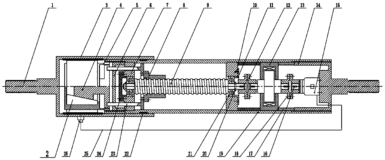
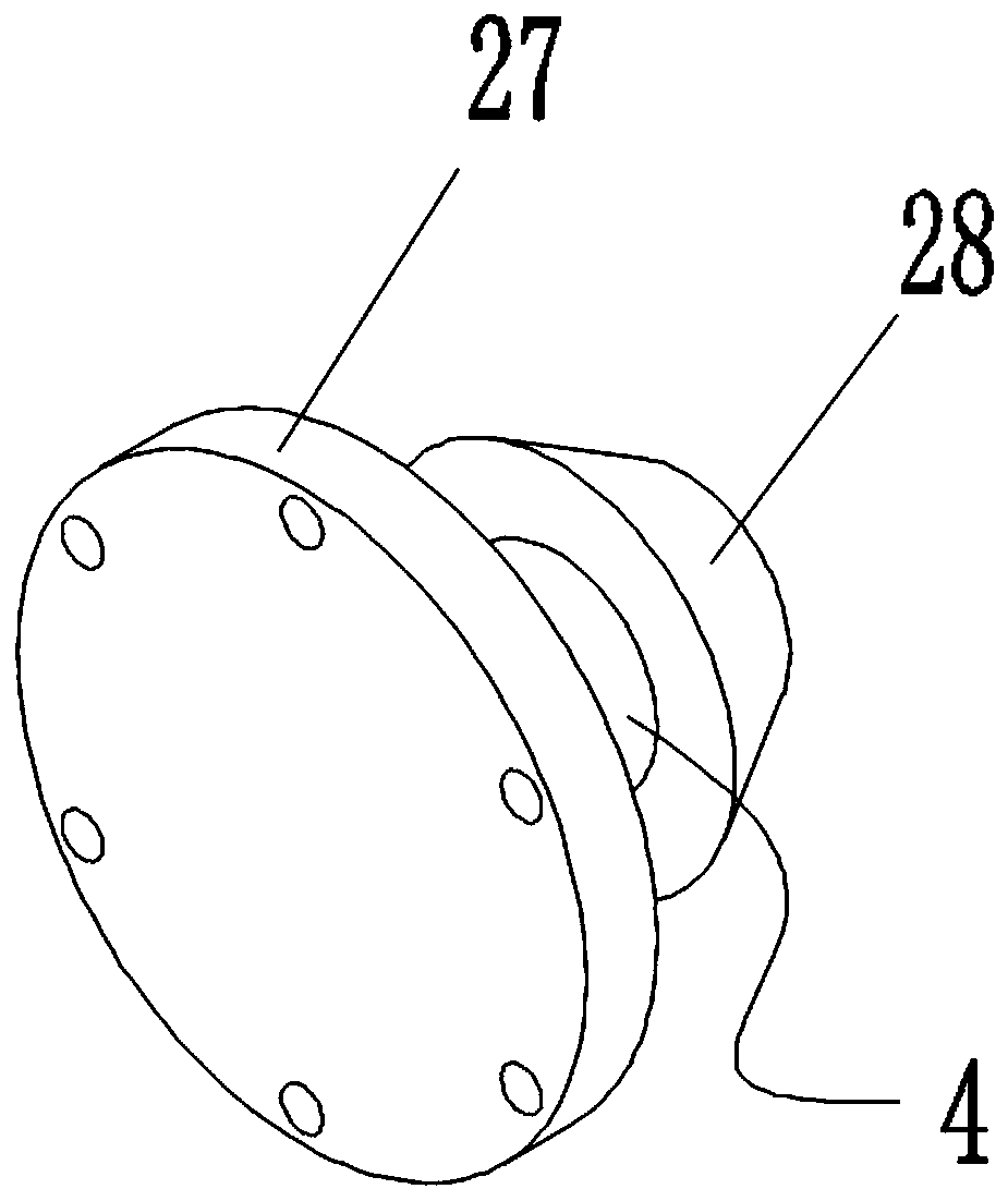
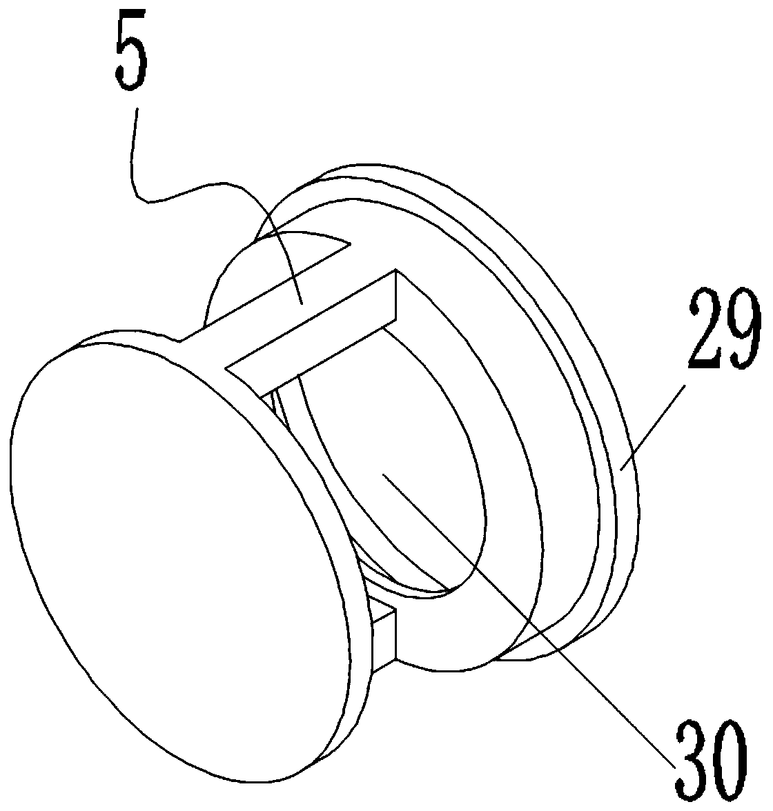
[0030] figure 1 It is a schematic diagram of the first structure of the present invention; figure 2 It is a structural schematic diagram of the piston propulsion block of the present invention; image 3 It is a schematic diagram of the structure of the piston ring of the present invention; as shown in the figure; a new type of broadband vibration damping device, including a support sleeve 19 and a piston outer cylinder 1 outside the support sleeve 19; the inner edge of the support sleeve 19 supports the sleeve 19 Axial direction (the axial direction is figure 1 The horizontal direction shown in ) is sequentially provided with a drive motor 15, a rotary magneto-rheological damper 13 and a ball screw assembly; the piston outer cylinder 1 is provided with a piston ring 5 fixedly connected to the end of the support sleeve 19 The inside of the piston ring 5 is provided with a wedge block 2; the end of the ball screw assembly is provided with a piston propulsion block 4 for movin...


PUM


Abstract

The invention discloses a novel broadband vibration damping device which comprises a supporting sleeve and a piston outer cylinder arranged outside the supporting sleeve in a sleeving mode. A drivingmotor, a rotary magnetorheological damper and a ball screw assembly are sequentially arranged in the supporting sleeve in the axial direction of the supporting sleeve; a piston ring fixedly connectedwith the end part of the supporting sleeve is arranged in the piston outer cylinder, and a wedge-shaped block with a trapezoidal section is arranged in the piston ring; the end part of the ball screwassembly is provided with a piston propelling block which is used for moving in the axial direction of the piston ring and then extruding the wedge-shaped block to expand circumferentially; and a friction plate is fixedly installed between the wedge-shaped block and the piston outer cylinder. According to the vibration damping device in the technical scheme, the pressure stability is realized through the rotary magnetorheological damper during working, the counter lock effect of the structure is guaranteed, the positive pressure is adjusted according to different working condition requirements, the friction coefficient of the embedded friction plate of the outer cylinder is changed, the required coulomb resistance is obtained, and the vibration damping performance is improved.

Description

technical field [0001] The invention relates to the field of mechanical vibration reduction, in particular to a novel broadband vibration reduction device. Background technique [0002] The damping coefficient of most existing damping mechanisms is closely related to the speed and has limited suppression effect on high-frequency vibration; the traditional rubber damper is greatly affected by temperature and cannot provide better damping effect at low frequencies; the existing hydraulic damper The vibration method cannot achieve better vibration reduction in low-amplitude and high-frequency working conditions; the piezoelectric adaptive vibration reduction device has a complex mechanism, high cost, and high energy consumption; some studies have applied magnetorheological technology to semi-active vibration reduction. However, the suppression effect of the magneto-rheological damper at high-frequency vibration is not ideal, and its speed has little influence, so it cannot meet...

Claims


Application Information

Patent Timeline
IPC IPC(8): F16F9/53F16F9/32
CPCF16F9/3207F16F9/3214F16F9/535
Inventor 董小闵宋现宇周正木李彪石开元
Owner CHONGQING UNIV
Learn More