Supercharge Your Innovation With Domain-Expert AI Agents!

Laser welding system for power batteries

A technology of laser welding and power battery, which is applied in the direction of laser welding equipment, welding equipment, metal processing equipment, etc., which can solve the large demand for new energy power battery production, large size and specification of new energy power battery, and power battery production demand. Great increase and other problems, to achieve the effect of reducing labor production and replacement costs, efficient welding, and improving production speed and efficiency

Active Publication Date: 2018-08-17
深圳市大族锂电智能装备有限公司
View PDF11 Cites 5 Cited by
  • Summary
  • Abstract
  • Description
  • Claims
  • Application Information

AI Technical Summary

Problems solved by technology

[0002] The development of new energy vehicles continues to grow. At the same time as the advantages and share of the global new energy vehicle market are expanding, the country has also introduced relevant measures for the development and innovation of new energy, especially new energy vehicles, which has triggered the production demand for new energy power batteries. The size and specifications of new energy power batteries are also getting larger and larger; the existing laser welding system cannot meet the requirements of the above-mentioned huge increase in the production demand of power batteries
[0003] At the same time, the battery positioning jig is driven by the rotary table and linear type. At the same time, the size and weight of the power battery will also affect the size and weight of the battery positioning jig. The heavier the battery positioning jig is, the bigger the battery positioning jig is. The movement (rotation) accuracy and speed of the positioning fixture movement method will be reduced to varying degrees

Method used


Image

  • Laser welding system for power batteries
  • Laser welding system for power batteries
  • Laser welding system for power batteries

Examples


Embodiment Construction

[0024] Now in conjunction with the accompanying drawings, the preferred embodiments of the present invention will be described in detail.

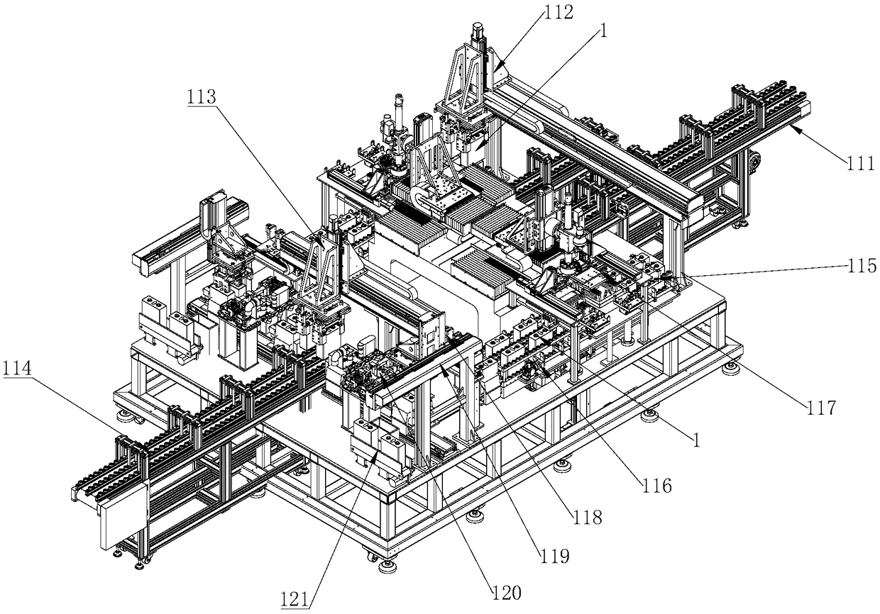
[0025] Such as figure 1 As shown, the present invention provides a preferred embodiment of a laser welding system for a power battery.

[0026] A laser welding system for a power battery 1, including a material feeding flow line 111, a feeding manipulator 112, a material unloading manipulator 113, and a material unloading logistics line 114, and the laser welding system also includes a material transfer channel 115 and a material transfer mechanism 116 , Welding mechanism 117 and detection mechanism 118; Wherein, described material shifting channel 115 is arranged between loading material streamline 111 and unloading material streamline 114, and is provided with welding station and detection station, described material shifting mechanism 116 is arranged on the material pulling channel 115, the welding mechanism 117 is arranged on the weld...


PUM


Abstract

The invention relates to the field of power battery welding, in particular to a laser welding system for power batteries. The laser welding system comprises a material shifting flow channel, a material shifting mechanism, a welding mechanism and a detection mechanism, wherein the material shifting flow channel is arranged between a feeding logistics line and a discharging logistics line and is provided with a welding station and a detection station, the material shifting mechanism is arranged on the material shifting flow channel, the welding mechanism is arranged on the welding station, and the detection mechanism is arranged on the detection station. According to the laser welding system which is arranged in an integrated mode, the power batteries can be efficiently welded, in addition,the structure layout mode can adapt to square power batteries with different specifications and size, and therefore the labor production and remodel cost of customers can be greatly lowered; and meanwhile, the positioning precision of the power batteries can be improved, so that the welding precision can be guaranteed, and therefore the production speed can be increased, and the production efficiency can be improved.

Description

technical field [0001] The invention relates to the field of power battery welding, in particular to a laser welding system for power batteries. Background technique [0002] The development of new energy vehicles continues to grow. At the same time as the advantages and share of the global new energy vehicle market are expanding, the country has also introduced relevant measures for the development and innovation of new energy, especially new energy vehicles, which has triggered the production demand for new energy power batteries. The size and specification of new energy power batteries are also increasing; the existing laser welding system cannot meet the requirements of the above-mentioned huge increase in the production demand of power batteries. [0003] At the same time, the battery positioning jig is driven by the rotary table and linear type. At the same time, the size and weight of the power battery will also affect the size and weight of the battery positioning ji...

Claims


Application Information

Patent Timeline
IPC IPC(8): B23K26/21B23K26/70H01M50/267
CPCB23K26/21B23K26/702
Inventor 刘洪峰苏舟徐作斌杨迅何俊杰高云峰
Owner 深圳市大族锂电智能装备有限公司
Features
  • R&D
  • Intellectual Property
  • Life Sciences
  • Materials
  • Tech Scout
  • Unparalleled Data Quality
  • Higher Quality Content
  • 60% Fewer Hallucinations
Learn More