
Multi-dimensional ultrasonic tool system with tool head action space being quadric surface and method of multi-dimensional ultrasonic tool system

A quadratic surface, ultrasonic tool head technology, used in manufacturing tools, metal processing, metal processing equipment, etc., can solve the problems of generating elliptical motion trajectories, small changes in cutting points and cutting force directions, and single motion trajectories.

Active Publication Date: 2018-08-17
JILIN UNIV
View PDF25 Cites 4 Cited by
  • Summary
  • Abstract
  • Description
  • Claims
  • Application Information

AI Technical Summary

Problems solved by technology

[0003] The present invention provides a multi-dimensional ultrasonic tool system and method in which the working space of the tool head is a quadratic surface, so as to solve the problem in the prior art that the motion track of the tool head generated by the ultrasonic vibrator is single and cannot generate an elliptical motion track in any plane. problem, as well as the existing ultrasonic cutting machine tool, the problem of small changes in cutting point and cutting force direction

Method used


Image

  • Multi-dimensional ultrasonic tool system with tool head action space being quadric surface and method of multi-dimensional ultrasonic tool system
  • Multi-dimensional ultrasonic tool system with tool head action space being quadric surface and method of multi-dimensional ultrasonic tool system
  • Multi-dimensional ultrasonic tool system with tool head action space being quadric surface and method of multi-dimensional ultrasonic tool system

Examples


Embodiment Construction

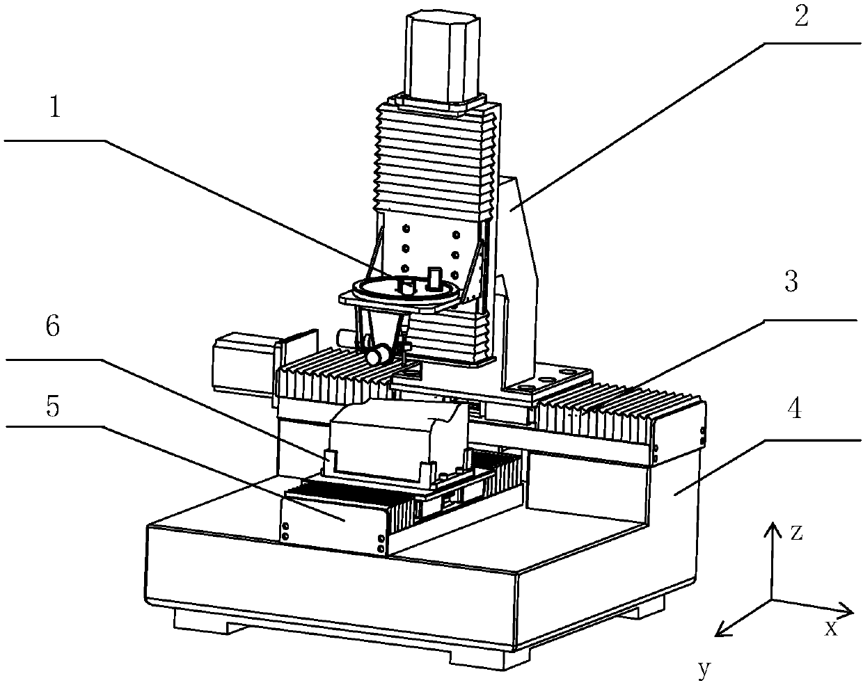
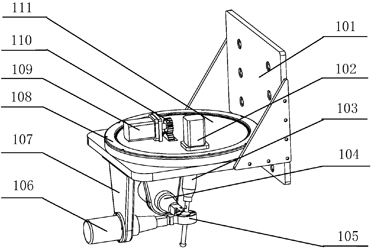
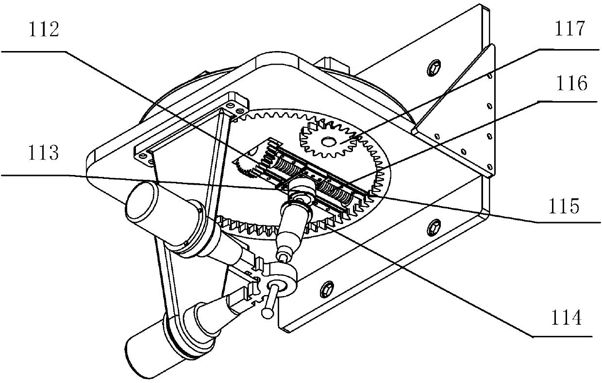
[0068] see figure 1 , including an ultrasonic tool head 1, a Z-direction moving device 2, an X-direction moving device 3, a base 4, a Y-direction moving device 5, and a fixture 6, the X-direction moving device 3 is laterally fixed and installed on the two bosses behind the base 4 , the motor of the X-direction moving device 3 is located on the left side of the main body of the X-direction moving device 3, the Y-direction moving device 5 is longitudinally fixed on the base 4, and the motor of the Y-direction moving device 5 is located in the X-direction moving device 3 In the space between the two bosses below, the fixture 6 is fixedly installed on the slide of the Y-direction moving device 5, and the Z-direction moving device 2 is vertically fixed on the slide of the X-direction moving device 3, so The ultrasonic tool head 1 is fixedly installed on the sliding plate of the Z-direction moving device 2, and the ultrasonic tool head 1 is located above the fixture 6;

[0069] lik...


PUM


Abstract

The invention relates to a multi-dimensional ultrasonic tool system with a tool head action space being a quadric surface and a method of the multi-dimensional ultrasonic tool system, and belongs to the field of machine manufacturing. An X-direction movement device is transversely and fixedly arranged on two bosses at the rear of a base; a motor of the X-direction movement device is located on theleft side of an X-direction movement device main body; a Y-direction movement device is longitudinally and fixedly arranged on the base; a motor of the Y-direction movement device is located in a gapbetween the two bosses below the X-direction movement device; a fixture is fixedly arranged on a slide carriage of the Y-direction movement device; a Z-direction movement device is vertically and fixedly arranged on a slide carriage of the X-direction movement device; and an ultrasonic tool head is fixedly arranged on a slide carriage of the Z-direction movement device and is located above the fixture. The multi-dimensional ultrasonic tool system and the method have the advantages that various movement tracks are output by the tool head under the action of an ultrasonic vibrator, so that themachining precision and the machining efficiency are improved, the service life of a cutter is prolonged, and more complex curved surfaces which can not be machined by a traditional machine tool can be machined.

Description

technical field [0001] The invention belongs to the field of mechanical manufacturing, and in particular relates to a multi-dimensional ultrasonic tool system and a control method in which the action space of a tool head is a quadric surface. Background technique [0002] With the rapid development of major fields such as aerospace, biomedicine, national defense, scientific instruments, and energy, the precision requirements for components in various fields, especially the surface precision of components, are getting higher and higher. In order to obtain the required high-precision smooth surface components, some scholars at home and abroad have carried out a lot of research on the technical field of ultrasonic vibration machining in recent years, including one-dimensional ultrasonic vibration machining, two-dimensional ultrasonic vibration machining, three-dimensional ultrasonic vibration machining. Ultrasonic vibration machining, etc. Although many scholars have obtained a...

Claims


Application Information

Patent Timeline
Patent Type & Authority Applications(China)
IPC IPC(8): B23Q1/44B23Q15/22
CPCB23Q1/44B23Q15/22
Inventor 冀世军张超赵继贺秋伟代汉达杨记龙
Owner JILIN UNIV
Learn More