
Shot blasting machine

A technology of shot blasting machine and friction plate, which is applied in the direction of abrasive jetting machine tools, metal processing equipment, used abrasive processing devices, etc., can solve the problem of long time-consuming recycling work, improve the effect of rust removal and reduce the time-consuming recycling Effect

Active Publication Date: 2019-07-30
CHONGQING QINGLAN MACHINERY MFG
View PDF5 Cites 1 Cited by
  • Summary
  • Abstract
  • Description
  • Claims
  • Application Information

AI Technical Summary

Problems solved by technology

[0005] The purpose of the present invention is to provide a shot blasting machine to solve the problem of long time-consuming recovery work caused by the prior art

Method used


Image

  • Shot blasting machine
  • Shot blasting machine

Examples


Embodiment

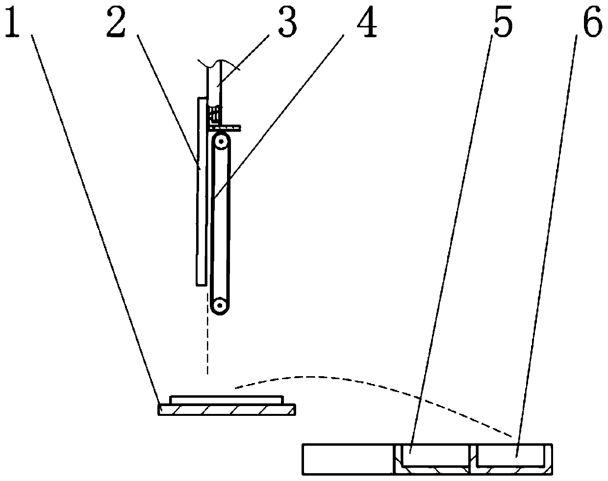
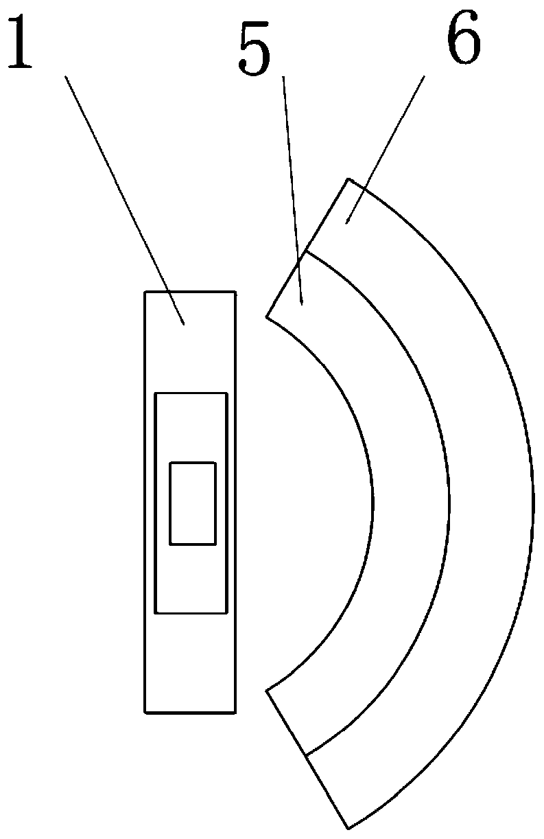
[0017] Embodiment: the shot blasting machine in this scheme, as figure 1 and figure 2 As shown, it includes a vertical acceleration device, a conveying device 1 for conveying products, and a recovery device, and the accelerating device is located above the conveying device 1 . The acceleration device includes a friction plate 2 and an acceleration conveyor belt. The friction plate 2 is made of elastic materials such as rubber or nylon, and the acceleration conveyor belt is located on one side of the friction plate 2 . The acceleration conveyor belt includes an acceleration belt, a driving roller and a driven roller. The acceleration belt is sheathed on the driving roller and the driven roller. The acceleration belt is parallel to the friction plate 2 , and there is an acceleration gap between the acceleration belt and the friction plate 2 . Cotton cloth is fixedly connected to the side of the friction plate 2 close to the acceleration belt, and a number of accelerated abrasi...


PUM


Abstract

The invention belongs to the field of shot blasting devices, and specifically discloses a shot blasting machine, which includes a vertical acceleration device, a conveying device for conveying products, and a recovery device. The accelerating device is located above the conveying device, and the accelerating device includes a friction plate and an accelerating conveyor belt. The friction plate is made of elastic material, and the acceleration conveyor belt is located on one side of the friction plate. The acceleration conveyor belt includes an acceleration belt, a driving roller and a driven roller. The acceleration belt is set on the driving roller and the driven roller, and the acceleration belt is parallel to the friction plate. There is an acceleration gap between the acceleration belt and the friction plate, and the recovery device is located on the side of the acceleration device close to the acceleration belt. The device can provide the steel shot with a higher impact velocity, improve the derusting effect of the steel shot at the same time, and can well screen the normal steel shot and the worn steel shot, thereby reducing the time-consuming recovery of the steel shot.

Description

technical field [0001] The invention belongs to the field of shot blasting devices, and in particular relates to a rust removal shot blasting machine. Background technique [0002] Shot blasting refers to throwing the pellets onto the working surface at a high speed and a certain angle by a mechanical method, allowing the pellets to impact the working surface, and then cleaning the pellets and The cleaned-up impurities are recovered separately and the pellets can be reused. Compared with other surface treatment technologies, it is faster and more effective. At the same time, the shot blasting machine is used with a dust collector, and the smoke and dust and attachments generated during the work process are recycled and treated in a unified manner, which is more environmentally friendly. [0003] According to the structure of the casting carrier, the shot blasting machine is divided into drum type, chain plate type, rotary table type, trolley type, squirrel cage type and han...

Claims


Application Information

Patent Timeline
IPC IPC(8): B24C3/02B24C9/00
CPCB24C3/02B24C9/006
Inventor 苏亚君
Owner CHONGQING QINGLAN MACHINERY MFG
Features
  • Generate Ideas
  • Intellectual Property
  • Life Sciences
  • Materials
  • Tech Scout
  • Unparalleled Data Quality
  • Higher Quality Content
  • 60% Fewer Hallucinations
Learn More