Positioning device and method based on depth vision and robot

A positioning device and depth sensor technology, applied in two-dimensional position/channel control, instruments, manipulators, etc., can solve the problems of complex visual simultaneous positioning algorithm and large consumption of processor computing resources, so as to improve navigation efficiency and reduce computing power. The effect of resources

Pending Publication Date: 2018-08-17
AMICRO SEMICON CORP
View PDF8 Cites 29 Cited by
  • Summary
  • Abstract
  • Description
  • Claims
  • Application Information

AI Technical Summary

Problems solved by technology

The process of VSLAM is performed using the image data captured by one or more oblique cameras in the navigation system of the mobile robot to map the environment and precisely locate the position of the mobile robot, however the combination a

Method used


Image

  • Positioning device and method based on depth vision and robot
  • Positioning device and method based on depth vision and robot
  • Positioning device and method based on depth vision and robot

Examples


Embodiment Construction

[0032] The specific embodiment of the present invention will be further described below in conjunction with accompanying drawing:

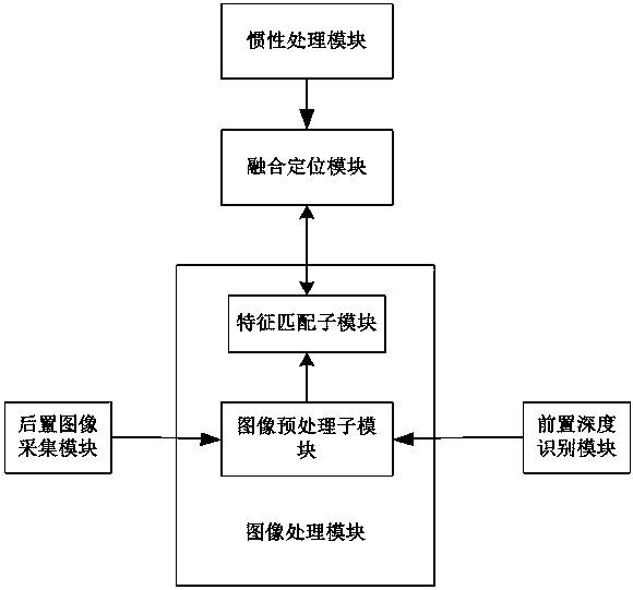
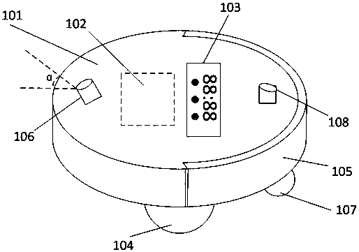
[0033] A positioning device based on depth vision in the embodiment of the present invention is implemented in the form of a robot, including mobile robots such as sweeping robots and AGVs. In the following, it is assumed that the positioning device is installed on the cleaning robot. However, those skilled in the art will appreciate that the configurations according to the embodiments of the present invention can be extended to be applied to mobile terminals, in addition to being used specifically for mobile robots.

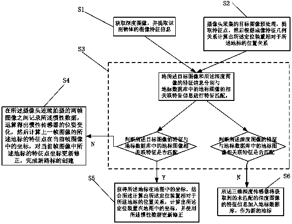
[0034] In the implementation of the present invention, those skilled in the art can easily know that in the process of executing vslam, a small map is buffered according to the feature points of the input image, and then the positional relationship between the current frame and the map is calculated. The map here is only a temporar...


PUM


Abstract

The invention discloses a positioning device and method based on depth vision and a robot. The positioning device is a movable vision positioning device which comprises a rear image collection module,a depth recognition module, an image processing module, an inertia processing module and an integrating positioning module. The rear image collection module is used for collecting landmark images forachieving positioning, the depth recognition module is used for recognizing the ground and objects on the ground, the image processing module comprises an image preprocessing submodule and a featurematching submodule and is used for processing image information input by the rear image collection module and the depth recognition module, the inertia processing module is used for sensing displacement information of an inertia sensor in real time, and the integrating positioning module is used for integrating environment information obtained by sensor modules for achieving positioning. Comparedwith the prior art, a three-dimensional depth sensor installed on the front portion provides new address information for a camera with the face inclined backwards in real time to complete positioningin a matching mode, accordingly, computing resources in the positioning navigation process are reduced, and the synchronous positioning efficiency is improved.

Description

technical field [0001] The invention relates to a positioning method and device, in particular to a positioning device, a positioning method and a robot based on depth vision. Background technique [0002] Three-dimensional (3D) depth capture systems extend traditional photography into a third dimension. While a 2D image obtained from a conventional camera indicates color and brightness at each (x,y) pixel, a 3D point cloud obtained from a 3D depth sensor indicates the distance to the object surface at each (x,y) pixel (z). In this way, the 3D sensor provides a measurement of the third spatial dimension z. 3D systems obtain depth information directly rather than relying on perspective, relative size, occlusion, texture, parallax, and other cues to detect depth. Direct (x, y, z) data is particularly useful for computer interpretation of image data. For example, the 3D point cloud data collected by the depth camera is projected onto a 2D plane to obtain 2D projection data,...

Claims


Application Information

Patent Timeline
IPC IPC(8): B25J5/00B25J9/16G05D1/02
CPCG05D1/0238G05D1/027B25J5/007B25J9/1676B25J9/1697
Inventor 赖钦伟
Owner AMICRO SEMICON CORP
Why Eureka
Try Eureka