Two-degree-of-freedom microgripper

A technology of micro-clamping and degree of freedom, which is applied in the direction of collets, micro-manipulators, manipulators, etc., can solve the problems of limiting the application range of micro-grippers and failing to meet the application fields of micro-grippers, and achieve measurement and real-time feedback , Improve static and dynamic characteristics, improve clamping stability and precision

Active Publication Date: 2018-08-17
TIANJIN UNIV
View PDF5 Cites 11 Cited by
  • Summary
  • Abstract
  • Description
  • Claims
  • Application Information

AI Technical Summary

Problems solved by technology

[0003] Most of the traditional micro grippers have only one degree of freedom, which cannot meet the application fields that have higher requirements for the degree of freedom of micro grippers, which seriously limits the application range of micro grippers

Method used


Image

  • Two-degree-of-freedom microgripper
  • Two-degree-of-freedom microgripper
  • Two-degree-of-freedom microgripper

Examples


Embodiment Construction

[0019] The present invention will be further described below in conjunction with the accompanying drawings.

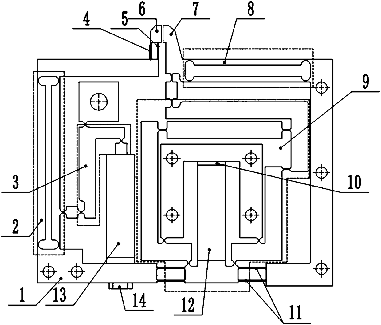
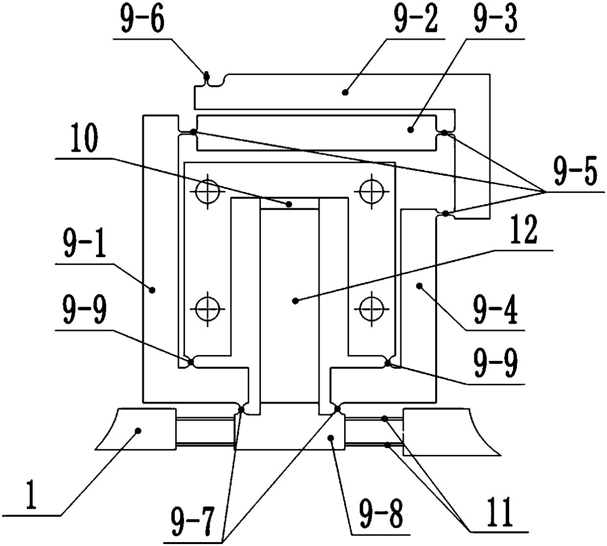
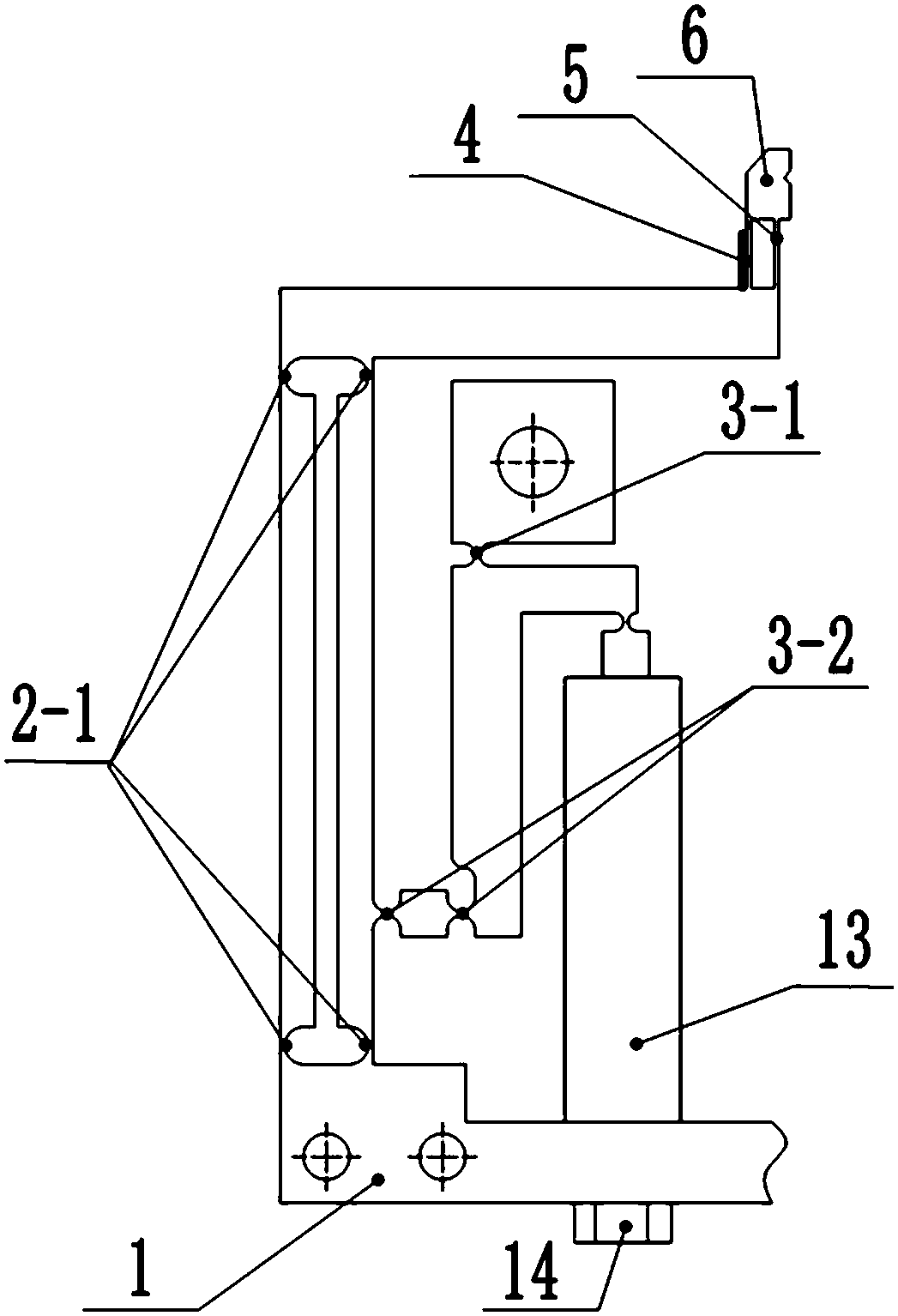
[0020] see Figure 1 to Figure 5 , a two-degree-of-freedom micro-gripper, which is integrally formed by plate wire cutting, including a lever displacement amplification mechanism 3, a differential displacement amplification mechanism 9 and a base body 1, a lever displacement amplification mechanism 3 and a differential displacement The enlargement mechanism 9 is respectively located on the left and right sides of the holder.

[0021] The differential displacement amplifying mechanism 9 is provided with an input rod 9-8 connected to the substrate 1, an L-shaped rod 9-1, 9-2, 9-4 and a connecting rod 9-3 parallel to the X axis; the input rod A flexible parallel double-plate mechanism I11 connected with the base body 1 is formed at both ends of the member 9-8, and a piezoelectric ceramic driver I12 is provided between the input rod member 9-8 and the base body 1, and the...


PUM


Abstract

The invention discloses a two-degree-of-freedom microgripper. The microgripper is of an asymmetrical structure integrally formed by linearly cutting a panel, and comprises a differential displacementmagnifying mechanism, a lever displacement magnifying mechanism and a base body, wherein the differential displacement magnifying mechanism is arranged on the right side of a center line of the gripper; the lever displacement magnifying mechanism is arranged on the left side of the center line of the gripper; the differential displacement magnifying mechanism is provided with an L-shaped rod pieceI, an L-shaped rod piece II, an L-shaped rod piece III, an input rod piece and a horizontal rod piece; the lever displacement magnifying mechanism and the base body are connected by adopting a flexible hinge III; an input end and an output end are arranged at two ends of the lever displacement magnifying mechanism; and the input end of the lever displacement magnifying mechanism is driven througha piezoelectric ceramic actuator II. The two-degree-of-freedom microgripper provided by the invention is small in volume and compact in structure, has two degrees of freedom, low manufacturing cost,and larger displacement magnifying times, can realize clamping force measurement and feedback, and can be applicable to different application fields.

Description

technical field [0001] The invention belongs to the field of micro device assembly, in particular to a two-degree-of-freedom micro gripper. Background technique [0002] In recent years, with the vigorous development of the microelectronics industry, the development of the microelectronics industry has become an important symbol to measure the comprehensive strength of a country, and an important guarantee to promote the sustainable development of the national economy and the security of the national strategic basic industry. With the continuous development of the microelectronics industry, its related industry devices are constantly developing towards miniaturization, high performance and high integration, and the quality requirements for assembly and operation are becoming more and more stringent. Therefore, the quality and efficiency of micro device packaging are put forward higher requirement. [0003] Most of the traditional micro-grippers have only one degree of freed...

Claims


Application Information

Patent Timeline
IPC IPC(8): B25J7/00B25J15/00B25J15/02
CPCB25J7/00B25J15/00B25J15/0253
Inventor 时贝超王福军赵兴玉梁存满霍至琛田延岭
Owner TIANJIN UNIV
Why Eureka
Try Eureka