
Brake exchange mechanism for intelligent climbing robot

An exchange mechanism and robot technology, applied in the field of robots, can solve the problems of control accuracy and reliability, high production and maintenance costs, poor stability of braking force output, etc., and achieves low operating energy consumption, simple structure, and braking force output. stable effect

Inactive Publication Date: 2018-08-17
CHANGZHOU COLLEGE OF INFORMATION TECH
View PDF0 Cites 0 Cited by
  • Summary
  • Abstract
  • Description
  • Claims
  • Application Information

AI Technical Summary

Problems solved by technology

[0002] At present, in climbing robots, stepping robots and stepping operation equipment, in order to improve the operation stability and control accuracy of the equipment, it is necessary to equip such equipment with a braking mechanism for controlling the operation state of the equipment. The braking equipment used in the equipment is often realized based on brake pads, brake shoes and other mechanisms. Although it can effectively meet the needs of the braking operation during operation, it will be different to varying degrees during the braking process. There are poor braking force output stability, poor braking response accuracy, high energy consumption during braking, and poor braking force retention capability, which lead to a greater impact on the current control accuracy and reliability of this type of equipment. In addition, in order to improve the braking control accuracy and other requirements, it is often necessary to cause the currently used braking mechanism to have a complex structure, high production and maintenance costs, high labor intensity, and low work efficiency. Therefore, in response to this phenomenon, it is urgent to develop A brand-new low-cost, high-precision braking device dedicated to climbing robots, stepping robots and stepping operating equipment to meet the needs of actual use and create great social and economic benefits

Method used

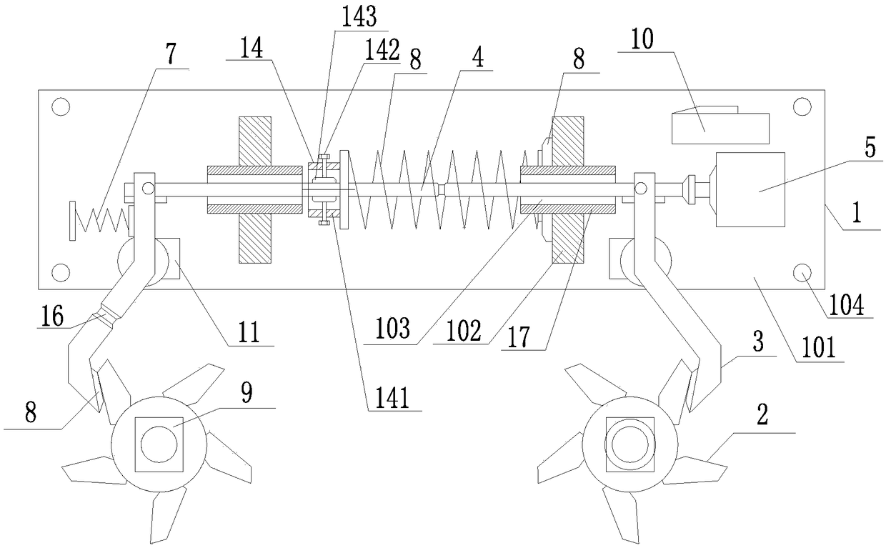
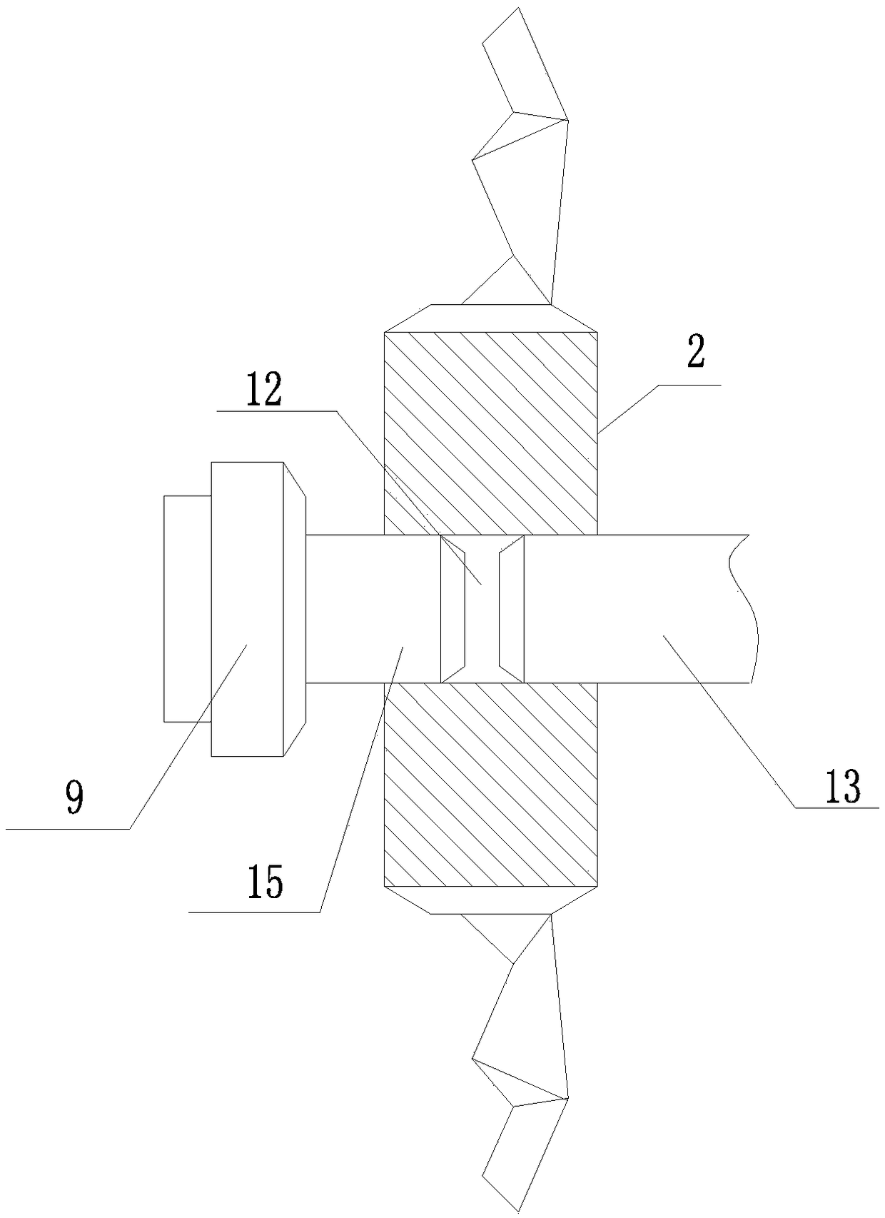
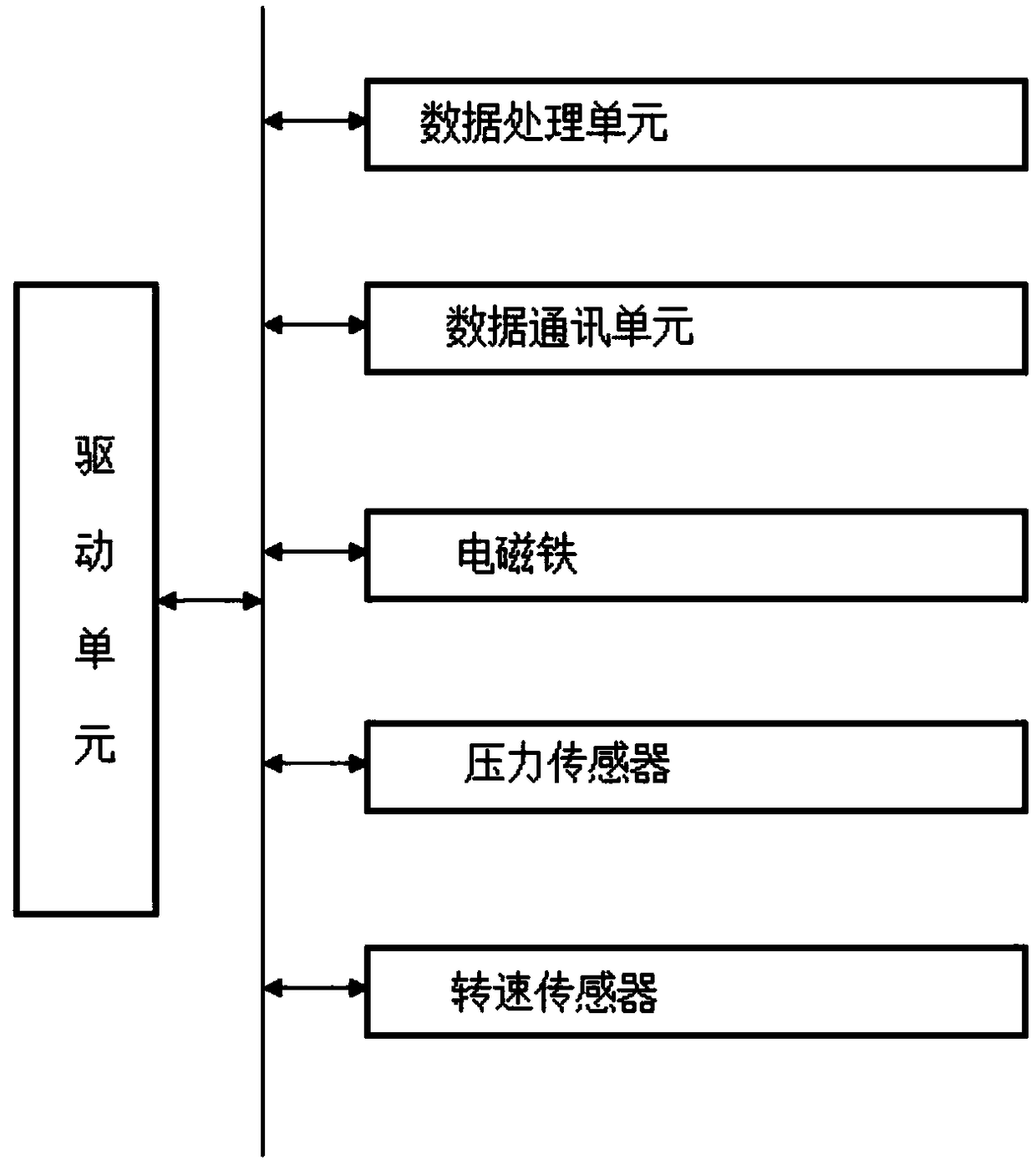

Image

  • Brake exchange mechanism for intelligent climbing robot
  • Brake exchange mechanism for intelligent climbing robot
  • Brake exchange mechanism for intelligent climbing robot

Examples


Embodiment Construction

[0021] In order to make the technical means, creative features, goals and effects achieved by the present invention easy to understand, the present invention will be further described below in conjunction with specific embodiments.

[0022] Such as figure 1 A brake exchange mechanism for an intelligent climbing robot described in —3, comprising a load frame 1, a ratchet 2, a pawl 3, a push-pull rod 4, an electromagnet 5, a pressure spring 6, a return spring 7, a pressure sensor 8. The rotational speed sensor 9 and the control system 10, wherein the carrying frame 1 includes a bottom plate 101 and a support plate 102, at least two support plates 102 are installed on the upper end surface of the bottom plate 101 and are vertically distributed with the upper end surface of the bottom plate 101, and on each support plate 102 Through-holes 103 are provided and coaxially distributed, and the push-pull rod 4 is slidingly connected with the support plate 102 through the through-hole 1...


PUM


Abstract

The invention relates to a brake exchange mechanism for an intelligent climbing robot. The brake exchange mechanism comprises a bearing machine frame, ratchets, detents, a push-pull rod, an electromagnet, a pressure-bearing spring, a reset spring, pressure sensors, rotation speed sensors and a control system, wherein the bearing machine frame comprises a bottom plate and supporting plates, the push-pull rod is slidably connected with the supporting plates through through holes, the electromagnet is connected with the end of the push-pull rod, and the side surface of the push-pull rod is hingedto the ends of the detents. The detents, the electromagnet and control system are all installed on the bottom plate, and the control system is electrically connected with the electromagnet, the pressure sensor and the rotation speed sensors correspondingly. The brake exchange mechanism can effectively improve the reliability and precision of the braking operation, and the running energy consumption of the braking operation can be effectively reduced.

Description

technical field [0001] The invention relates to a brake exchange mechanism for an intelligent climbing robot, which belongs to the technical field of robots. Background technique [0002] At present, in climbing robots, stepping robots and stepping operation equipment, in order to improve the operation stability and control accuracy of the equipment, it is necessary to equip such equipment with a braking mechanism for controlling the operation state of the equipment. The braking equipment used in the equipment is often realized based on brake pads, brake shoes and other mechanisms. Although it can effectively meet the needs of the braking operation during operation, it will be different to varying degrees during the braking process. There are poor braking force output stability, poor braking response accuracy, high energy consumption during braking, and poor braking force retention capability, which lead to a greater impact on the current control accuracy and reliability of ...

Claims


Application Information

Patent Timeline
Patent Type & Authority Applications(China)
IPC IPC(8): B25J19/00
CPCB25J19/0004
Inventor 莫盛秋陈大朋顾志华
Owner CHANGZHOU COLLEGE OF INFORMATION TECH
Learn More