Underwater bionic robotic fish driven by fluid conveying pipe

A technology of robotic fish and flow tubes, which is applied in underwater operation equipment, transportation and packaging, and emission reduction based on propulsion, can solve problems such as impacting the vicinity, large environmental disturbances, and robots being trapped underwater, and achieve a better life Status and habits, low overall energy consumption, and the effect of reducing the risk of being trapped

Pending Publication Date: 2018-08-17
HUAZHONG UNIV OF SCI & TECH
View PDF5 Cites 6 Cited by
  • Summary
  • Abstract
  • Description
  • Claims
  • Application Information

AI Technical Summary

Problems solved by technology

However, most of the existing underwater robots use motors to drive the propellers to push the robots forward, which inevitably has some defects, such as: the wake vortex caused by the rotation of the propellers greatly disturbs the

Method used


Image

  • Underwater bionic robotic fish driven by fluid conveying pipe

Examples


Embodiment Construction

[0028] In order to make the object, technical solution and advantages of the present invention clearer, the present invention will be further described in detail below in conjunction with the accompanying drawings and embodiments. It should be understood that the specific embodiments described here are only used to explain the present invention, not to limit the present invention. In addition, the technical features involved in the various embodiments of the present invention described below can be combined with each other as long as they do not constitute a conflict with each other.

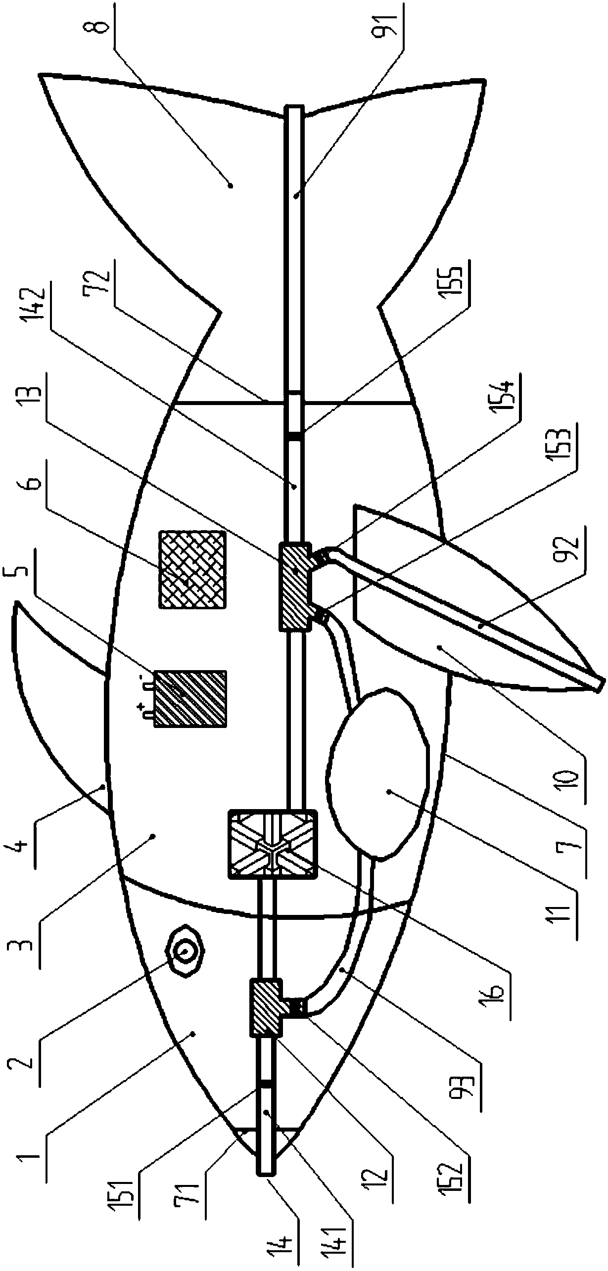
[0029] Such as figure 1 As shown, the underwater bionic robotic fish of the present invention includes: fish head 1, fisheye camera 2, fish body 3, dorsal fin 4, power supply 5 (this embodiment is a lithium battery), controller 6, sealed cavity 7, the first First seal ring 71, second seal ring 72, tail fin 8, tail fin flow hose 91, pectoral fin flow hose 92, water bag flow hose 93, pectoral fin...


PUM


Abstract

The invention discloses an underwater bionic robotic fish driven by a fluid conveying pipe. The underwater bionic robotic fish includes a fish head, a fish body, a dorsal fin, a tail fin, pectoral fins, a water sac, a water pump, a fluid conveying pipe system, a controller and a power supply. The interior of the fish body is a closed cavity, and the water pump, the controller and the fluid conveying pipe system are all installed in the cavity. Flutter occurs when the internal flow of a fluid conveying hose of the tail fin exceeds the critical flow velocity, so that the tail fin is driven to swing to provide power for the fish to move forwards. A fluid hose of the pectoral fins also flutters when the internal flow exceeds the critical flow velocity, so that the left and right pectoral finsswing up and down, and the steering of the fish can be controlled while the propulsion power is provided. The water storage capacity in the water sac is controlled by the water pump and the fluid conveying pipe system, and the weight of the fish body is increased or reduced so as to achieve the sinking and floating of the fish body. The required power for electrical equipment is provided by the power supply, and various motion forms of the bionic fish is controlled by the controller. According to the underwater bionic robotic fish driven by the fluid conveying pipe, the fish movement can be simulated, the disturbance to underwater creatures is reduced, and the risk of being trapped is reduced.

Description

technical field [0001] The invention belongs to the field of underwater detection robots, and more specifically relates to an underwater bionic robot fish driven by a delivery tube. Background technique [0002] At present, the development of underwater robots is quite common, and huge costs have been invested. These underwater robots are mainly used in the detection of underwater pollution sources, the survey of water quality, the search and rescue of marine accident ships, the observation of seabed fish and other fields. However, most of the existing underwater robots use motors to drive the propellers to push the robots forward, which inevitably has some defects, such as: the wake vortex caused by the rotation of the propellers greatly disturbs the environment and affects nearby fish schools; the complex ecological environment at the bottom is prone to Cause the propeller to be entangled by aquatic plants or waste, and cause the robot to be trapped at the bottom of the w...

Claims


Application Information

Patent Timeline
IPC IPC(8): B63C11/52B63H19/04
CPCB63C11/52B63H19/04Y02T70/5236
Inventor 代胡亮刘智远王琳张岚斌江天力吴攀陈伟林时想
Owner HUAZHONG UNIV OF SCI & TECH
Why Eureka
Try Eureka