
Automatic box and lid feeding mechanism

A technology for sending boxes and covers, which is applied in the direction of conveyors, unstacking and packaging of objects, which can solve the problems of high risk, mechanical accidental injury, accidents, etc., to reduce mechanical failures, ensure production and processing safety, and improve work efficiency Effect

Pending Publication Date: 2018-08-17
SHENZHEN NUOFENG OPTOELECTRONICS EQUIP
View PDF0 Cites 6 Cited by
  • Summary
  • Abstract
  • Description
  • Claims
  • Application Information

AI Technical Summary

Problems solved by technology

[0002] The automatic box and cover feeding mechanism is a new type of automatic equipment system. It is a multi-purpose automatic equipment with novel structure, simple and flexible operation, high efficiency and strong applicability. Automatically complete the operation of the entire assembly line, so as to achieve the state of automatic box delivery and cover delivery, which is frequently used in modern life and industry; there are certain disadvantages in the use of existing automation equipment. First, manual automatic box picking Putting the cover on the automation equipment is not only inefficient, but also requires a lot of work. The most serious thing is that it is dangerous. When the box or cover is manually removed, it is inevitable that you will be accidentally injured by the machine and accidents will occur. , brought a certain influence

Method used

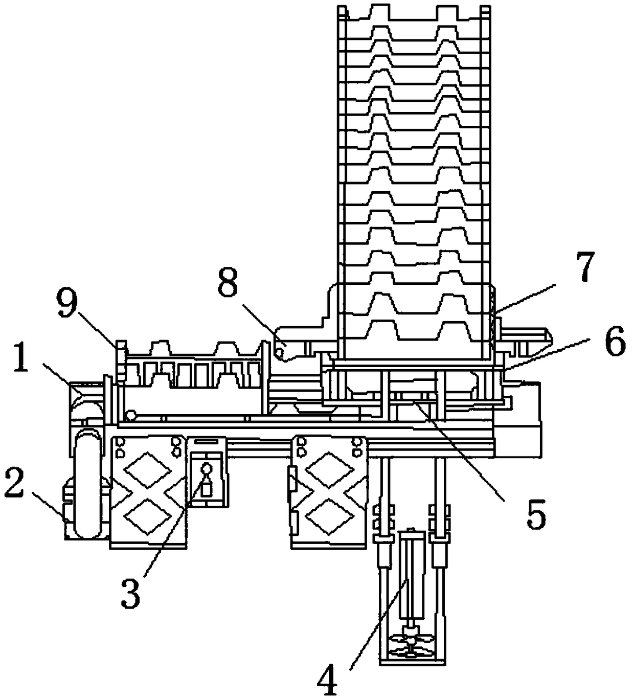
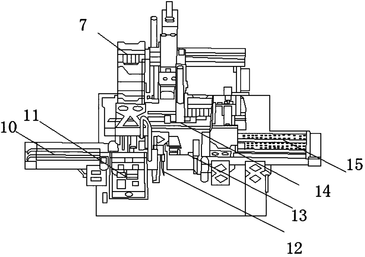
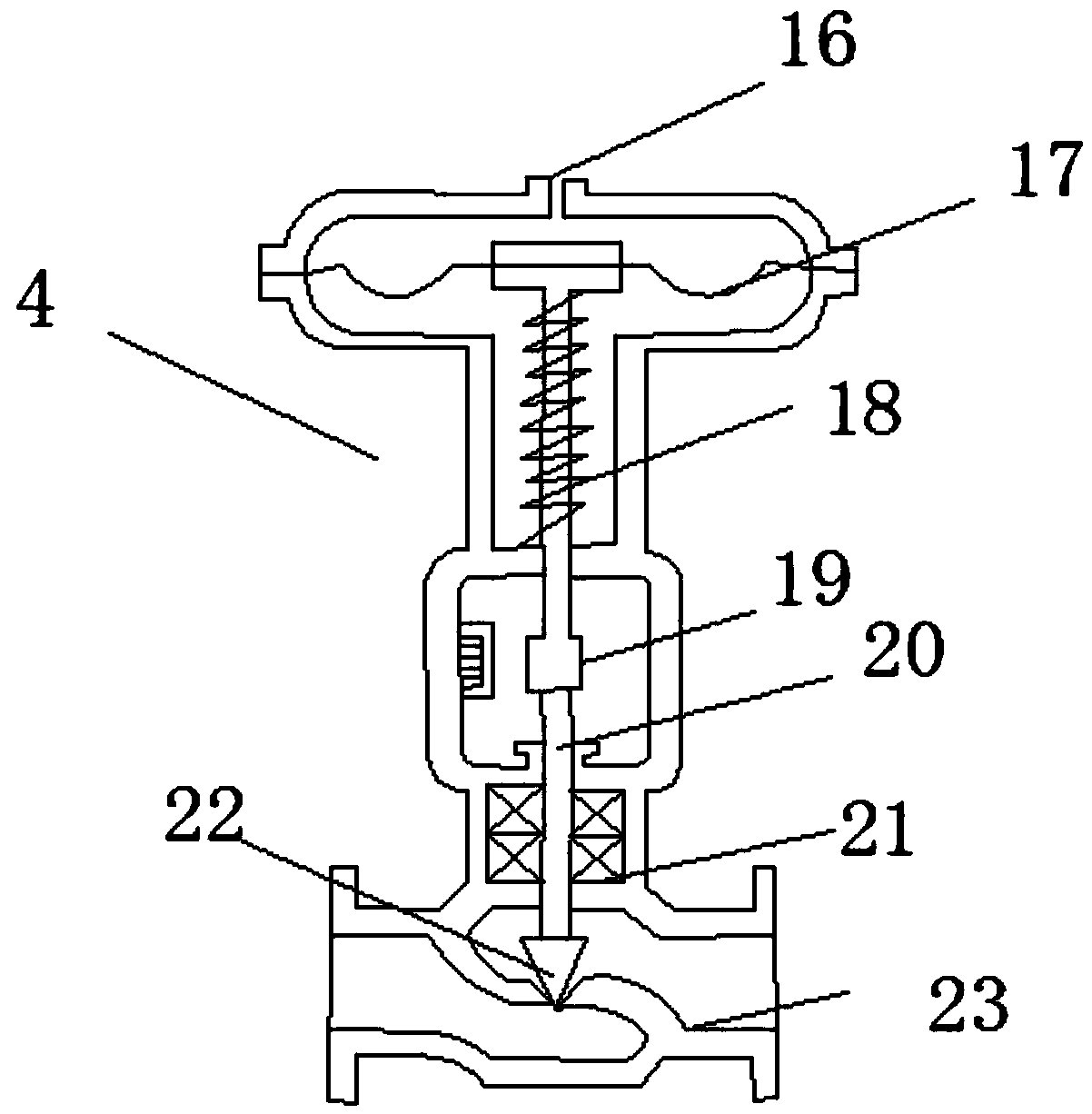

Image

  • Automatic box and lid feeding mechanism
  • Automatic box and lid feeding mechanism
  • Automatic box and lid feeding mechanism

Examples


Embodiment Construction

[0031] The technical solutions in the embodiments of the present invention will be clearly and completely described below in conjunction with the accompanying drawings in the embodiments of the present invention. Obviously, the described embodiments are only a part of the embodiments of the present invention, rather than all the embodiments. Based on the embodiments of the present invention, all other embodiments obtained by those of ordinary skill in the art without creative work shall fall within the protection scope of the present invention.

[0032] See Figure 1-5 , The present invention provides a technical solution: an automatic box feeding and cover feeding mechanism, comprising a conveyor belt 1, the outer surface of the lower end of the conveyor belt 1 is fixedly connected with a geared motor 2, and the outer surface of the geared motor 2 is fixedly connected with a speed regulator 3 , The outer surface of the governor 3 is movably connected with a sub-box cylinder 4, t...


PUM


Abstract

The invention discloses an automatic box and lid feeding mechanism. The automatic box and lid feeding mechanism comprises a conveying belt. The outer surface of the lower end of the conveying belt isfixedly connected with a gear motor. One side of the outer surface of the gear motor is fixedly connected with a speed regulator. The outer surface of the speed regulator is movably connected with a box distributing air cylinder. The outer surface of the upper end of the box distributing air cylinder is movably connected with a box pulling air cylinder. The outer surface of the upper end of the box pulling air cylinder is movably connected with a clamp air cylinder. The outer surface of the upper end of the clamp air cylinder is movably connected with a box and lid holding frame. A position limit air cylinder is arranged at one side of the outer surface of the box and lid holding frame. A to-be-fetched box position is arranged on the outer surface of the upper end of the speed regulator. The outer and inner surfaces of the lower end of the box and lid holding frame are fixedly connected with an incoming material assembly line. According to the automatic box and lid feeding mechanism, in the fields of mechanical engineering and automation, an automatic boxing machine is provided with an automatic box and lid feeding and discharging mechanism, matching is achieved, using is flexible,the equipment continuity is improved, labor input is reduced, and the phenomenon that staff are accidentally injured by machines when taking and placing boxes and lids is avoided.

Description

Technical field [0001] The invention relates to the field of automation equipment, in particular to an automatic box feeding mechanism. Background technique [0002] The automatic box feeding and lid feeding mechanism is a new type of automatic equipment system with novel structure, simple and flexible operation, high efficiency, and strong applicability. It is a multi-purpose automatic equipment with strong applicability. The operation of the entire assembly line is automatically completed, so as to achieve the state of automatic box feeding and lid feeding. It is used in modern life and industry with a high frequency; the existing automation equipment has certain drawbacks when in use. First of all, manual automatic box removal Putting the cover on the automatic equipment is not only inefficient, but also has a large workload. The most serious is the high risk. When the box or cover is manually taken out, it is inevitable that accidents will occur by the machine accidentally an...

Claims


Application Information

Patent Timeline
IPC IPC(8): B65B43/44B65B43/46B65B7/28B65G59/06
CPCB65B7/2807B65B43/44B65B43/46B65G59/067B65G2201/025
Inventor 张德梁庆远聂江江
Owner SHENZHEN NUOFENG OPTOELECTRONICS EQUIP
Learn More