
Edge member and construction method of steel concrete shear wall

A technology of concrete shear walls and edge components, which is applied to building components, building structures, walls, etc., can solve the problems of low production efficiency, troublesome coordination, and unseen problems, and achieve the improvement of building industrialization level, fast construction speed, The effect of improving performance

Active Publication Date: 2019-10-08
安徽威岩环保工程建设有限公司
View PDF8 Cites 0 Cited by
  • Summary
  • Abstract
  • Description
  • Claims
  • Application Information

AI Technical Summary

Problems solved by technology

[0005] However, the problems in this invention application are: the processing of the hemmed U-shaped steel plate arranged at the end of the wall is difficult, which is not conducive to industrial production, the production efficiency is low, and the cost is pushed up; the steel structure is exposed, and fireproof coating must be adopted, which not only increases cost, and how to coordinate the wall section with the concrete wall is also very troublesome; the embodiment only has "line-shaped" shear walls, and how to solve "T-shaped" and "L-shaped" shear walls must be quite difficult. Therefore, it is difficult for the invention application to be practicable
[0010] Most of the existing steel-concrete shear wall edge members and construction technologies use steel to enhance the performance of the shear wall structure, and there is no use of steel as both the reinforcement of the edge members of the shear wall and as an enhancement of the shear wall structure. At the same time, it can also be used as a fixing part without dismantling the formwork to achieve a multi-purpose effect, so as to improve the level of building industrialization and open up an implementation mode of high-efficiency and low-consumption prefabricated concrete shear wall structure buildings.

Method used


Image

  • Edge member and construction method of steel concrete shear wall
  • Edge member and construction method of steel concrete shear wall
  • Edge member and construction method of steel concrete shear wall

Examples


Embodiment 1

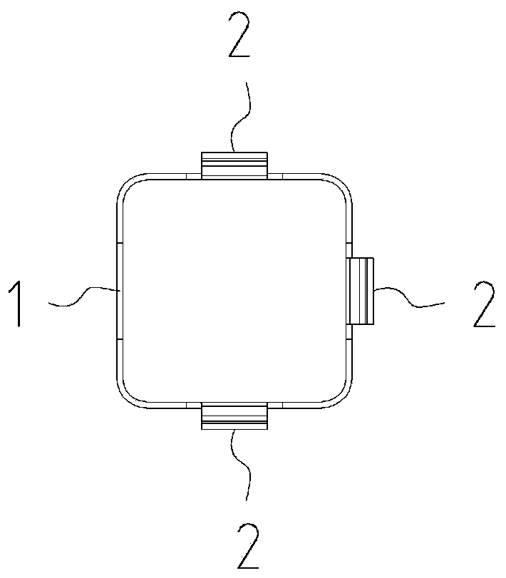
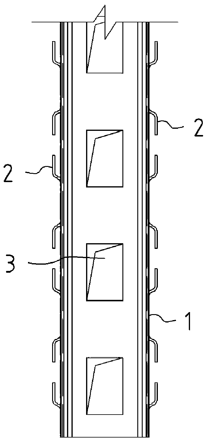
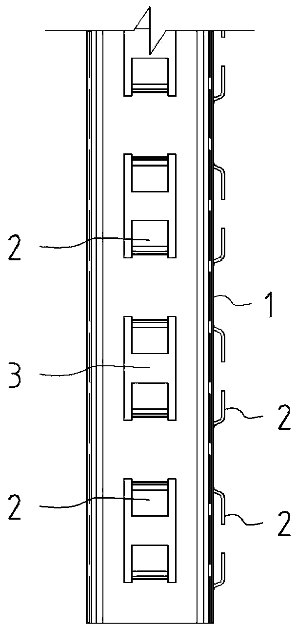
[0056] Example 1: Constructing the edge member of the concrete shear wall with open square steel pipe 1

[0057] Such as Figure 11 to Figure 17 as shown,

[0058] Step 1. Arranging open square steel pipe 1 and binding steel bars

[0059] According to the area of ​​the longitudinal force-bearing reinforcement required by the structural design, the opening square steel pipe 1 of the edge member of the shear wall is arranged according to the principle of equal strength. The connection between the upper and lower sides of the opening square steel pipe 1 can be inserted with a small section square steel pipe After welding or bolting, additional steel bars can also be added at the joint to realize the lap joint connection under the force of the structure;

[0060] The longitudinal reinforced steel bars of the edge members of the shear wall are all replaced by open-hole square steel pipes 1. The horizontal steel bars include the stirrups 81 of the edge members and the horizontally...

Embodiment 2

[0065] Example 2: Using thin-walled steel trusses 4 to construct edge members of concrete shear walls

[0066] Such as Figure 21 to Figure 23 As shown, when the shear wall connecting beam is connected with the edge member, the use of open square steel pipe 1 will affect the reinforcement arrangement of the shear wall connecting beam. In this case, the thin-walled steel truss 4 is used to construct the edge member of the concrete shear wall ,

[0067] Step 1. Arranging thin-walled steel trusses 4 and binding steel bars

[0068] The thin-walled steel trusses 4 of the edge members of the shear wall are arranged according to the area of ​​the longitudinal force-bearing reinforcement required by the structural design, and the connection between the upper and lower sides of the thin-walled steel trusses 4 can be made of small-section thin-walled steel trusses. 4. Welding or bolting after inserting, it is also possible to add additional steel bars at the joint to realize the lap j...

Embodiment 3

[0074] Embodiment three, the construction process of shear wall body

[0075] Such as Figure 18 to Figure 20 As shown, the concrete shear wall body is constructed with thin-walled steel trusses 4,

[0076] Step 1. Arranging thin-walled steel trusses 4 and binding steel bars

[0077] According to the area of ​​vertically distributed steel bars in the shear wall body that needs to be set in structural design, the thin-walled steel trusses 4 of the shear wall body are arranged according to the principle of equal strength, and the connection between the upper and lower sides of the thin-walled steel trusses 4 can be small The cross-section thin-walled steel truss 4 is welded or bolted after being inserted, and additional steel bars can also be added at the joint to realize the lap joint connection of the structural force;

[0078] The vertically distributed steel bars of the shear wall body are all replaced by thin-walled steel trusses 4, and the horizontally distributed steel ...


PUM


Abstract

The invention discloses a shape steel concrete shear wall edge member and a construction method thereof and belongs to the field of construction engineering. The shape steel concrete shear wall edge member mainly comprises an open square steel pipe, a thin-walled shape steel truss, wall body horizontal distribution steel bars, edge member stirrups, cement pressure plates, self-tapping nails, longitudinal force-bearing steel bars of the shear wall edge member and the like. The open square steel pipe and the thin-walled shape steel truss serve as reinforcing bars of the shear wall edge member, can improve the performance of a shear wall, and meanwhile can further serve as fixing pieces of a disassembly-free formwork, thus one piece with multiple purposes is achieved, and in order to increasethe building industrialization level, the construction method, good in quality, high in construction speed, efficient and low in consumption, of a fabricated concrete shear wall structure building isprovided.

Description

technical field [0001] The invention belongs to the field of construction engineering, and relates to a concrete shear wall structure, in particular to an edge component of a steel concrete shear wall and a construction method. Background technique [0002] For a long time, in order to improve the performance of concrete shear wall structures, building structural engineering technicians and scientific researchers have achieved their goals by arranging steel in the edge components of concrete shear walls. He has done a lot of research work and achieved fruitful scientific research results. [0003] In recent years, with the demand for building industrialization and the rise of prefabricated buildings, research and technological innovations on the edge components of steel concrete shear walls used in prefabricated concrete structures have continued to emerge. The retrieved technical documents include: [0004] 1. The invention patent application of application publication num...

Claims


Application Information

Patent Timeline
Patent Type & Authority Patents(China)
IPC IPC(8): E04B2/60E04G21/00
Inventor 孟凡林
Owner 安徽威岩环保工程建设有限公司
Learn More