Hole plugging method of printed circuit board

A technology for printed circuit boards and circuit boards, which is applied in the fields of printed circuits, printed circuits, and printed circuit manufacturing. Uniform and flat appearance of plug holes

Active Publication Date: 2018-08-17
梅州金时裕科技有限公司
View PDF4 Cites 4 Cited by
  • Summary
  • Abstract
  • Description
  • Claims
  • Application Information

AI Technical Summary

Problems solved by technology

[0005] However, if the printed circuit board is directly plugged with ink, the air and organic solvents contained in the ink will cause voids in the ink after drying, and will crack to the orifice, resulting in chemicals and moisture in the subsequent process operations. The cracks enter the voids, resulting in poor plugging effect of the ink

Method used


Image

  • Hole plugging method of printed circuit board

Examples


Embodiment Construction

[0029] Below in conjunction with specific embodiment, further illustrate the present invention.

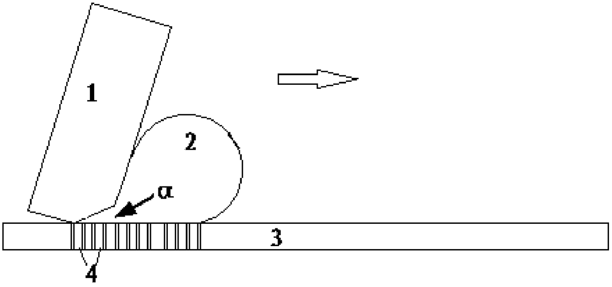
[0030] As shown in the figure, a plugging method of a printed circuit board is characterized in that the method comprises the following steps:

[0031] Step 1, preparation of plugging ink

[0032] Step 2, surface treatment of the printed circuit board, using a cleaning device to clean the circuit board (3) to be plugged to remove surface impurities;

[0033] Step 3, an air extraction device is arranged at the bottom of the cleaned circuit board in step 2, and the air extraction hole of the air extraction device is correspondingly arranged with the plug hole (4) of the circuit board;

[0034] Step 4, setting a stencil on the printing surface of the surface-treated circuit board in step 2, so that the filling port on the stencil is set correspondingly to the plug hole (4) of the circuit board;

[0035] Step 5, place the plug hole ink prepared in step 1 on the screen, move the scra...


PUM


Abstract

Disclosed is a hole plugging method of a printed circuit board. By virtue of preparation of hole plugging resin and a combination of an air extracting apparatus and a scraper, a plug hole is filled with resin ink on a screen plate, and final curing is performed. By virtue of the method, resin ink can uniformly cover a circuit and a base material, and the resin ink in the plug hole is high in saturation degree.

Description

technical field [0001] The invention relates to a hole plugging method of a printed circuit board. Background technique [0002] PCB, the Chinese name is printed circuit board, also known as printed circuit board, is an important electronic component, a support for electronic components, and a carrier for electrical connections of electronic components. Because it is made using electronic printing, it is called a "printed" circuit board. [0003] Printed boards have developed from single-layer to double-sided, multi-layer and flexible, and still maintain their own development trends. Due to the continuous development in the direction of high precision, high density and high reliability, continuous reduction in size, cost reduction and performance improvement, printed boards still maintain strong vitality in the development of future electronic equipment. [0004] With the development of miniaturization of assembly components, the wiring area and pattern design area of ​​PC...

Claims


Application Information

Patent Timeline
Patent Type & Authority Applications(China)
IPC IPC(8): H05K3/00H05K3/40
CPCH05K3/0094H05K3/40H05K2201/0959
Inventor 林木源顾龙
Owner 梅州金时裕科技有限公司
Why Eureka
Try Eureka