A mailbox device

A letter box and installation cavity technology, which is applied to shearing devices, cutters for shearing machine devices, manufacturing tools, etc., can solve the problems of low safety, hidden dangers, affecting the production and processing of letter boxes, etc., and achieves convenient operation and simple structure. Effect

Inactive Publication Date: 2019-07-26
PUJIANG HUIYI INTELLIGENT TECH CO LTD
View PDF7 Cites 0 Cited by
  • Summary
  • Abstract
  • Description
  • Claims
  • Application Information

AI Technical Summary

Problems solved by technology

[0002] Mailboxes are carriers for storing letters, and they are used in a wide range of applications. Therefore, the demand for production and processing of letter boxes also increases. When producing and processing letter boxes, it is often necessary to cut the body of the letter box. The current market cutting Equipment, in the process of use, it is not convenient to assemble and replace the knife body, which affects the normal use of the cutting equipment, thereby reducing the working efficiency of the cutting equipment. In addition, the existing cutting equipment has exposed knives and no protective measures. Low security, there are large potential safety hazards, affecting the production and processing of mailboxes

Method used


Image

  • A mailbox device
  • A mailbox device
  • A mailbox device

Examples


Embodiment Construction

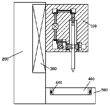
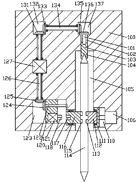
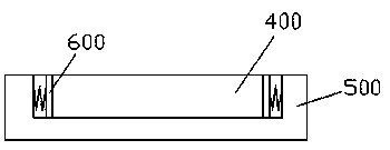
[0012] Combine below Figure 1-3 The present invention will be described in detail.

[0013] refer to Figure 1-3 , a letter box device according to an embodiment of the present invention includes a processing frame 100, the processing frame is installed on the right side end surface of the bracket 200 through the lifting device 300, and a device is fixed at the bottom position of the right side end surface of the bracket 200 The fixed seat 500, the top end surface of the fixed seat 500 is embedded with a fixed cavity 400, the left and right sides of the fixed cavity 400 are symmetrically fixed with elastic clamping plates 600, and the bottom end surface of the processing frame 100 is provided with There is an installation cavity 105, and a processing cutter body 114 is installed in rotation fit in the installation cavity 105, and a locking device for locking and fitting connection with the processing cutter body 114 is arranged in the inner wall of the right side of the inst...


PUM


Abstract

The invention discloses a letterbox device. The letterbox device comprises a processing rack; the processing rack is installed at the end face of the right side of a bracket through a lifting device;a mounting seat is fixedly arranged at the bottom position of the end face of the right side of the bracket; a mounting chamber is embedded inside the top end face of the mounting seat; the end facesof the left and right sides of the mounting chamber are symmetrically fixedly provided with elastic clamping plates; an installation chamber is formed inside the bottom end face of the processing rack; a processing cutter body is installed inside the installation chamber in a running fit manner; the inner wall of the right side of the installation chamber is internally provided with a locking andlinking member which is connected with the processing cutter body in a locking and matching manner; the inner wall body, positioned at the left side of the installation chamber, of the processing rackis internally provided with a slidable connection chamber; the wall body between the slidable connection chamber and the installation chamber is internally provided with a left rotating connector ina running fit manner; the end face of the left side of the left rotating connector is internally provided with a spline notch; a slidable connecting block is installed inside the slidable connection chamber in a sliding fit manner; and a first electromotor is fixedly arranged inside the end face of the right side of the slidable connecting block.

Description

technical field [0001] The invention relates to the field of mailbox equipment, in particular to a mailbox device. Background technique [0002] Mailboxes are carriers for storing letters, and they are used in a wide range of applications. Therefore, the demand for production and processing of letter boxes also increases. When producing and processing letter boxes, it is often necessary to cut the body of the letter box. The current market cutting Equipment, in the process of use, it is not convenient to assemble and replace the knife body, which affects the normal use of the cutting equipment, thereby reducing the working efficiency of the cutting equipment. In addition, the existing cutting equipment has exposed knives and no protective measures. The safety is low, and there is a big potential safety hazard, which affects the production and processing of mailboxes. Contents of the invention [0003] The object of the present invention is to provide a letter box device f...

Claims


Application Information

Patent Timeline
Patent Type & Authority Patents(China)
IPC IPC(8): B23D19/00B23D35/00B23Q11/00
CPCB23D19/00B23D35/004B23Q11/0078
Inventor 吴美俊
Owner PUJIANG HUIYI INTELLIGENT TECH CO LTD
Why Eureka
Try Eureka