Cooling device for film blowing equipment

A cooling device and equipment technology, which is applied in the field of cooling devices, can solve problems such as high pressure of viscous fluid film blanks, tearing of film bubbles, unstable shape of film bubbles, etc., and achieve the best effect of uniform effect

Active Publication Date: 2018-08-21
汕头市众鑫隆机械制造有限公司
View PDF4 Cites 3 Cited by
  • Summary
  • Abstract
  • Description
  • Claims
  • Application Information

AI Technical Summary

Problems solved by technology

[0002] In the production process of plastic packaging film, a film blowing machine is often used for processing and production. The molten resin material is extruded from the extrusion port of the die and pulled upwards. The hot film billet is cooled to form a relatively stable and highly elastic cylindrical film bubble. During the cooling process of the film billet, especially a section of the soft viscous film billet near the extrusion port, it is necessary to control a reasonable air flow The pressure, flow rate and uniformity of the air ring can prevent the irregular airflow output by the air ring from affecting the shape of the extrusion area of ​​the film blank; It is difficult to cool the film blank in the viscous flow state below the line by airflow. It is necessary to increase the airflow pressure and flow rate to increase the blowing height of the airflow. The high-speed airflow with large flow rate will easily cause the initial extrusion near the extrusion port. The viscous fluid state of the film blank is under too much pressure, which will bring about the adverse effects of unstable film bubble shape or tearing of the film bubble

Method used


Image

  • Cooling device for film blowing equipment
  • Cooling device for film blowing equipment
  • Cooling device for film blowing equipment

Examples


Embodiment

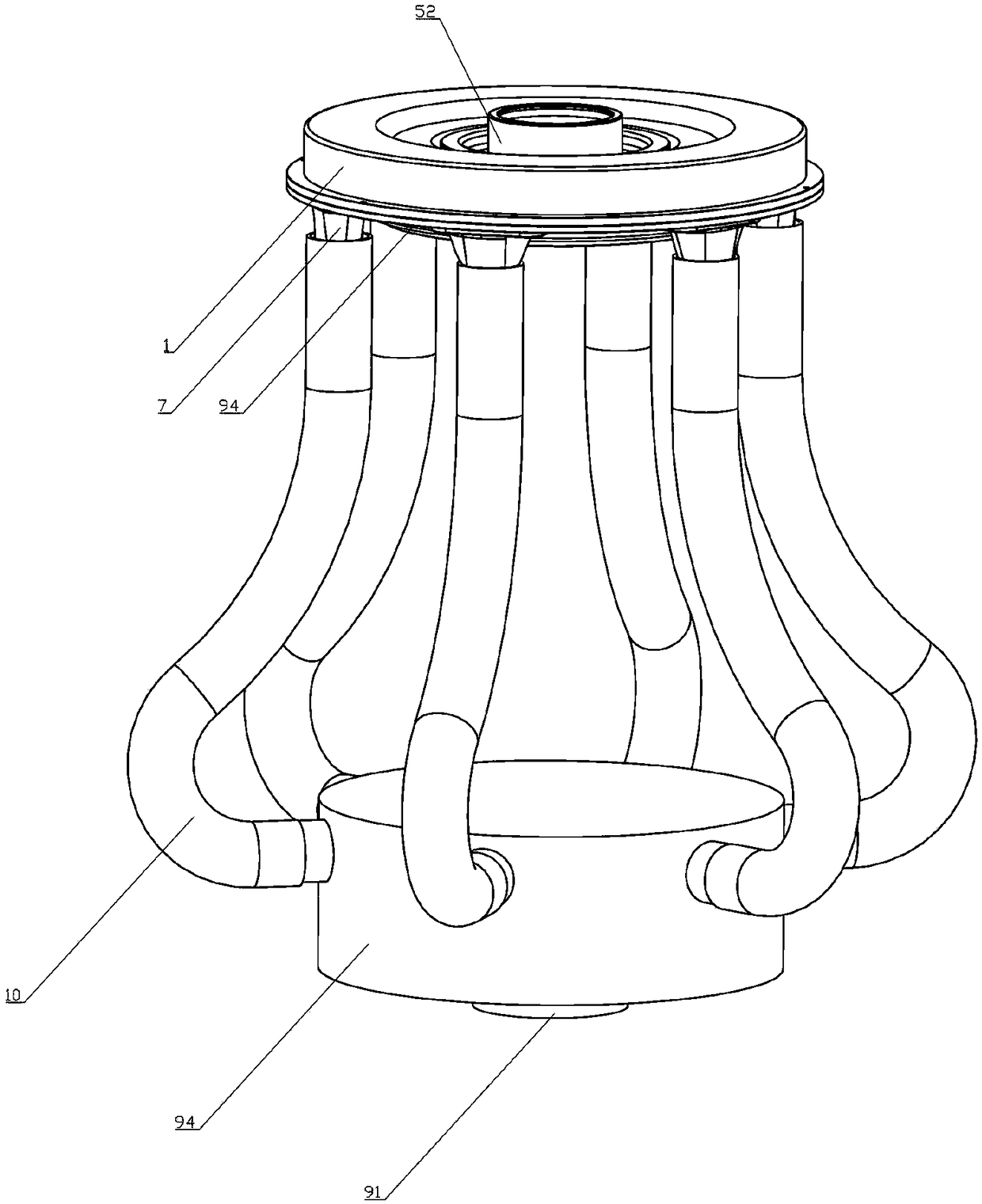
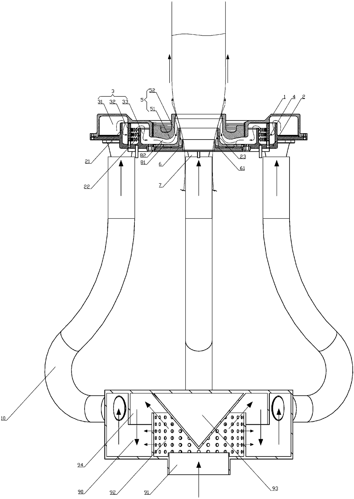
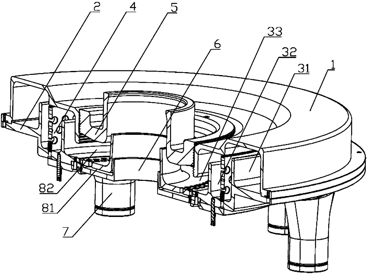
[0025] Such as Figure 1-3 As shown, a cooling device for film blowing equipment includes an air supply base 90, an air ring, and six air supply pipes 10. In the center of the air supply base 90, an upwardly facing air supply inlet 91 is provided, and the air supply inlet 91 is provided to the air supply through a flow diversion mechanism. The inner cavity of the air base supplies annular air flow, and the air supply pipe 10 is evenly arranged around the air supply base 90 and connected to the inner cavity of the air supply base and the annular main air duct 3;

[0026] Such as figure 2 As shown, the flow distribution mechanism includes a conical platform 93 collinear with the axis of the air supply inlet 91, an annular splitter plate 92, and an annular baffle 94, and the tip of the conical platform 93 on the inner cavity top wall of the air supply base 90 is downward. Pointing to the center of the air supply inlet 91, distribution holes are evenly arranged on the annular sp...


PUM


Abstract

The invention discloses a cooling device for film blowing equipment. An air supply inlet facing upwards is arranged right in the center of an air supply base, an annular air flow is supplied to an inner cavity of the air supply base through a flow splitting mechanism, an air supply pipe surrounds the air supply base evenly and is connected with the inner cavity of the air supply base and an annular main air duct, the annular main air duct diverts to the inner side to form a first-level annular air duct and a second-level annular air duct, outlets of the first-level annular air duct and the second-level annular air duct both face upwards and mutually come together, an inlet of the first-level annular air duct is peripherally arranged on an air discharge regulating ring in the form of an inlet aperture array and is mutually communicated with the second-level annular air duct, the air discharge regulating ring only regulates the space of the second-level annular air duct and regulates thevelocity of both the first-level annular air duct and the second-level annular air duct, the air discharge regulating ring is provided with a closing structure for closing the second-level annular air duct, and the annular main air duct directly supplies air to the first-level annular air duct in the closing state. The device improves the cooling stability of a film blank, particularly a primarily extruded viscous-state film blank, and meanwhile, the forming effect of the film blank near to the part of the frost line is improved.

Description

technical field [0001] The invention relates to the technical field of film blowing equipment, in particular to a cooling device for film blowing equipment. Background technique [0002] In the production process of plastic packaging film, a film blowing machine is often used for processing and production. The molten resin material is extruded from the extrusion port of the die and pulled upwards. The hot film billet is cooled to form a relatively stable and highly elastic cylindrical film bubble. During the cooling process of the film billet, especially a section of the soft viscous film billet near the extrusion port, it is necessary to control a reasonable air flow The pressure, flow rate and uniformity of the air ring can avoid the influence of the irregular airflow output by the air ring on the extrusion area of ​​the membrane blank; It is difficult to cool the film blank in the viscous flow area below the line by air flow. It is necessary to increase the air flow pres...

Claims


Application Information

Patent Timeline
Patent Type & Authority Applications(China)
IPC IPC(8): B29C55/28B29C35/16
CPCB29C35/16B29C55/28B29C2035/1658
Inventor 王茂陈浩裕
Owner 汕头市众鑫隆机械制造有限公司
Why Eureka
Try Eureka