Reduction treatment process for oil sludge at tank bottom

A treatment process and reduction technology, applied in sludge treatment, water/sludge/sewage treatment, dehydration/drying/thickened sludge treatment, etc., can solve the problem that the oil content of sludge is not guaranteed, cannot meet discharge standards, cleaning The effect is not obvious, etc., to achieve the effect of increasing the amount of processing and increasing the difficulty of processing

Inactive Publication Date: 2018-08-21
甘肃新鑫能源工程有限公司
View PDF6 Cites 7 Cited by
  • Summary
  • Abstract
  • Description
  • Claims
  • Application Information

AI Technical Summary

Problems solved by technology

[0003] In the prior art, the patent document "A "Cleaning + Centrifugation" Oil Sludge Treatment Process" (publication number: CN104817248A) discloses a process for treating oil sludge, through impurity removal pulping, cleaning and degreasing, and centrifugation to obtain The sludge with oil content ≤ 2% can meet the emission standards stipulated by

Method used


Image

  • Reduction treatment process for oil sludge at tank bottom

Examples


Embodiment 1

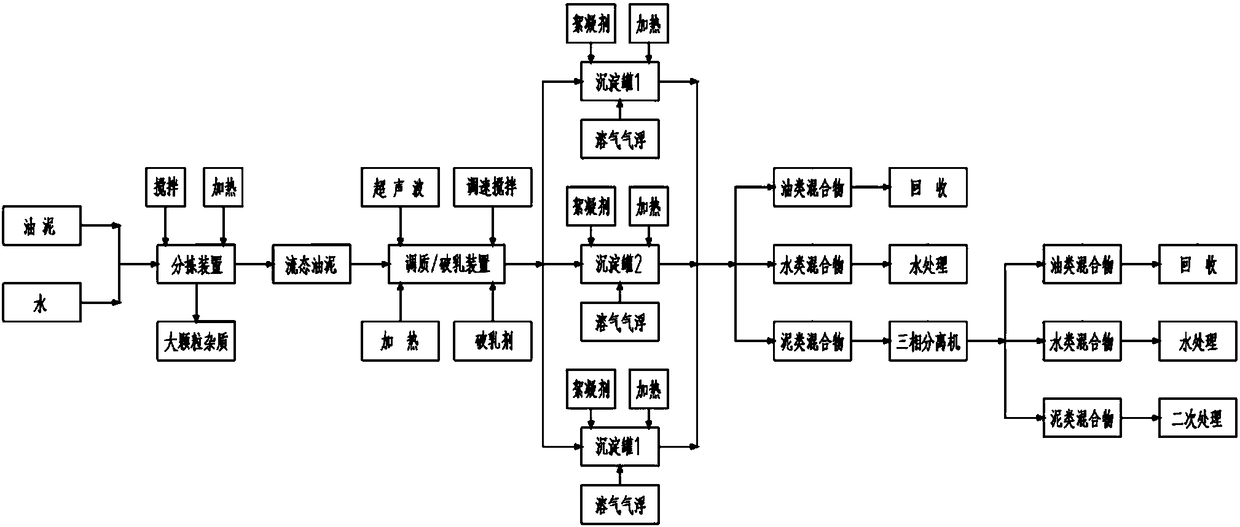
[0033] Take fluidized tank bottom sludge as an example. This kind of sludge will not have large particles of impurities, and it will be directly transported to the quenching and tempering demulsification tank through the mud pump, and an appropriate amount of water will be added according to the water content. According to the test data, the stirring, ultrasonic, and Heat to 40°C, add demulsifier, run for 10 minutes, raise the temperature to 60°C, and continue to run for 10 minutes. Transport the conditioned and demulsified oil sludge to the settling tank through a mud pump, add flocculant, after stirring, turn on the dissolved air flotation device, let it stand for 30 minutes, and take out the oil mixture and water mixture respectively. Heat the remaining mud mixture to 60°C, stir evenly, and transport it to the three-phase separation equipment through a mud pump to obtain oil mixture, water mixture, and mud mixture, achieving a reduction of more than 80%. Among them, the wat...

Embodiment 2

[0035] Taking the semi-fluid tank bottom sludge as an example, the sludge is first transported to the sorting device by mechanical force, a certain amount of water is added, stirred, and heated to 40°C to reduce the viscosity of the sludge and remove large particles of impurities to obtain fluid sludge . The fluid sludge is transported to the conditioning and tempering demulsification tank through the mud pump. According to the test data, start stirring, ultrasonic, heat to 40°C, add demulsifier, run for 10 minutes, raise the temperature to 60°C, and continue to run for 10 minutes. Transport the conditioned and demulsified oil sludge to the settling tank through a mud pump, add flocculant, after stirring, turn on the dissolved air flotation device, let it stand for 30 minutes, and take out the oil mixture and water mixture respectively. Heat the remaining mud mixture to 60°C, stir evenly, and transport it to the three-phase separation equipment through a mud pump to obtain oil...


PUM


Abstract

The invention discloses a reduction treatment process for oil sludge at tank bottom. The oil sludge at the tank bottom is decomposed into large-particle impurities, a water mixture, an oil mixture anda sludge mixture after being subjected to sorting, hardening-tempering demulsification, precipitation for layering and three-phase separation, wherein the large-particle impurities are subjected to landfilling or recycled after surface oil sludge is cleaned; the water mixture is recycled after water treatment; the oil mixture serves as fuel or an oil refining raw material; the sludge mixture is subjected to secondary treatment such as pyrolysis, brickmaking and the like according to oil content; therefore, the reduction treatment process for the oil sludge at the tank bottom is realized. Flow-state oil sludge is prepared, and oil, water and sludge phases are separated by hardening-tempering demulsification and run separately; in terms of precipitation for layering, the separated oil, water and sludge phases are layered under the actions of dissolved air flotation, a flocculant and gravity and collected respectively; in terms of three-phase separation, the sludge mixture obtained afterprecipitation for layering is re-separated by a three-phase centrifugal machine. 50% or more reduction can be realized through three times of reduction treatment, and the application prospect is quite broad.

Description

technical field [0001] The invention belongs to the technical field of oil sludge treatment, and in particular relates to a process method for reducing the amount of oil sludge at the bottom of a tank. Background technique [0002] There are many oil sludge treatment processes, such as solvent extraction, incineration, pyrolysis and other technologies. Each process has certain limitations, that is, each process has certain requirements for oil sludge. For example, solvent extraction requires relatively single sludge components, and incineration and pyrolysis Both require reduction post-processing. [0003] In the prior art, the patent document "A "Cleaning + Centrifugation" Oil Sludge Treatment Process" (publication number: CN104817248A) discloses a process for treating oil sludge, through impurity removal pulping, cleaning and degreasing, and centrifugation to obtain Sludge with oil content ≤ 2% can meet the emission standards stipulated by the state, but the disadvantage ...

Claims


Application Information

Patent Timeline
IPC IPC(8): C02F11/12C02F11/14C02F11/00
CPCC02F11/14C02F11/00C02F11/121C02F11/127
Inventor 齐加胜黄欣欣
Owner 甘肃新鑫能源工程有限公司
Why Eureka
Try Eureka