
Press-fit diversion sealing strip, diversion sealing wall and construction method thereof

A technology for sealing strips and walls, applied to walls, buildings, building components, etc., can solve the problems of poor sealing effect and inconvenient construction, and achieve the effect of low construction accuracy, strong adaptability and high elasticity

Active Publication Date: 2020-01-21
ARCHITECTURAL DESIGN & RES INST OF TSINGHUA UNIV +1
View PDF3 Cites 0 Cited by
  • Summary
  • Abstract
  • Description
  • Claims
  • Application Information

AI Technical Summary

Problems solved by technology

[0003] The purpose of the present invention is to provide a press-fit diversion sealing strip, a diversion sealing wall and its construction method, to solve the technical problems of poor sealing effect and inconvenient construction of traditional sealing means

Method used


Image

  • Press-fit diversion sealing strip, diversion sealing wall and construction method thereof
  • Press-fit diversion sealing strip, diversion sealing wall and construction method thereof
  • Press-fit diversion sealing strip, diversion sealing wall and construction method thereof

Examples


Embodiment 1

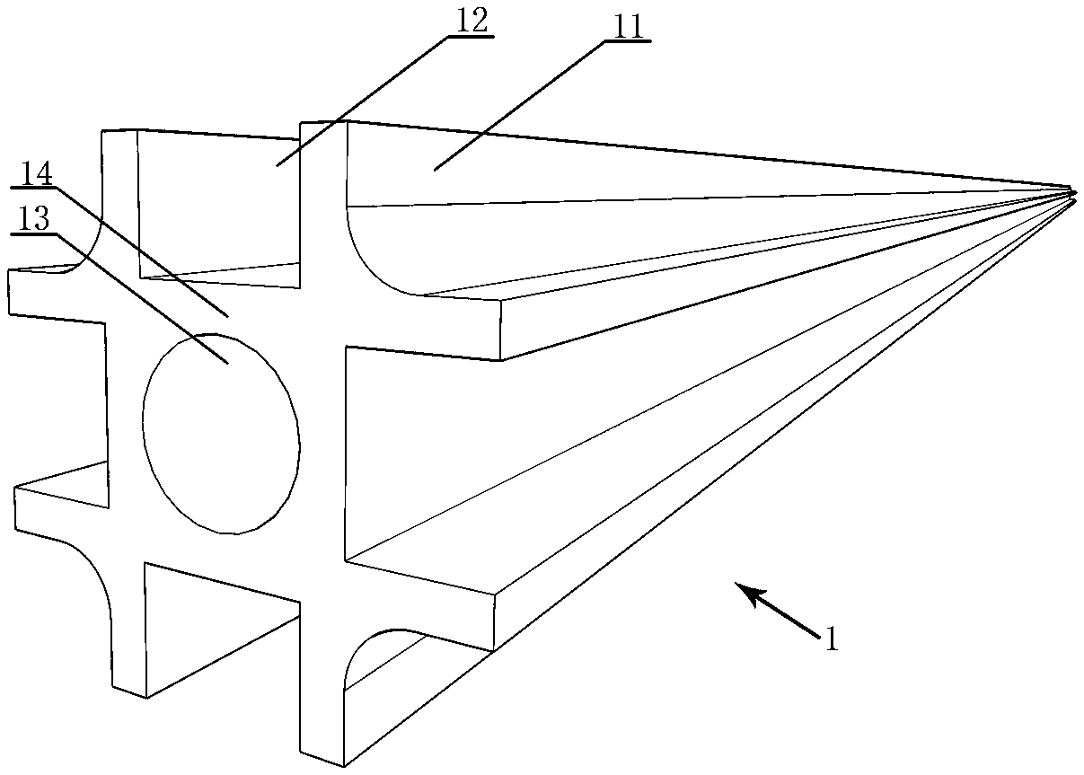
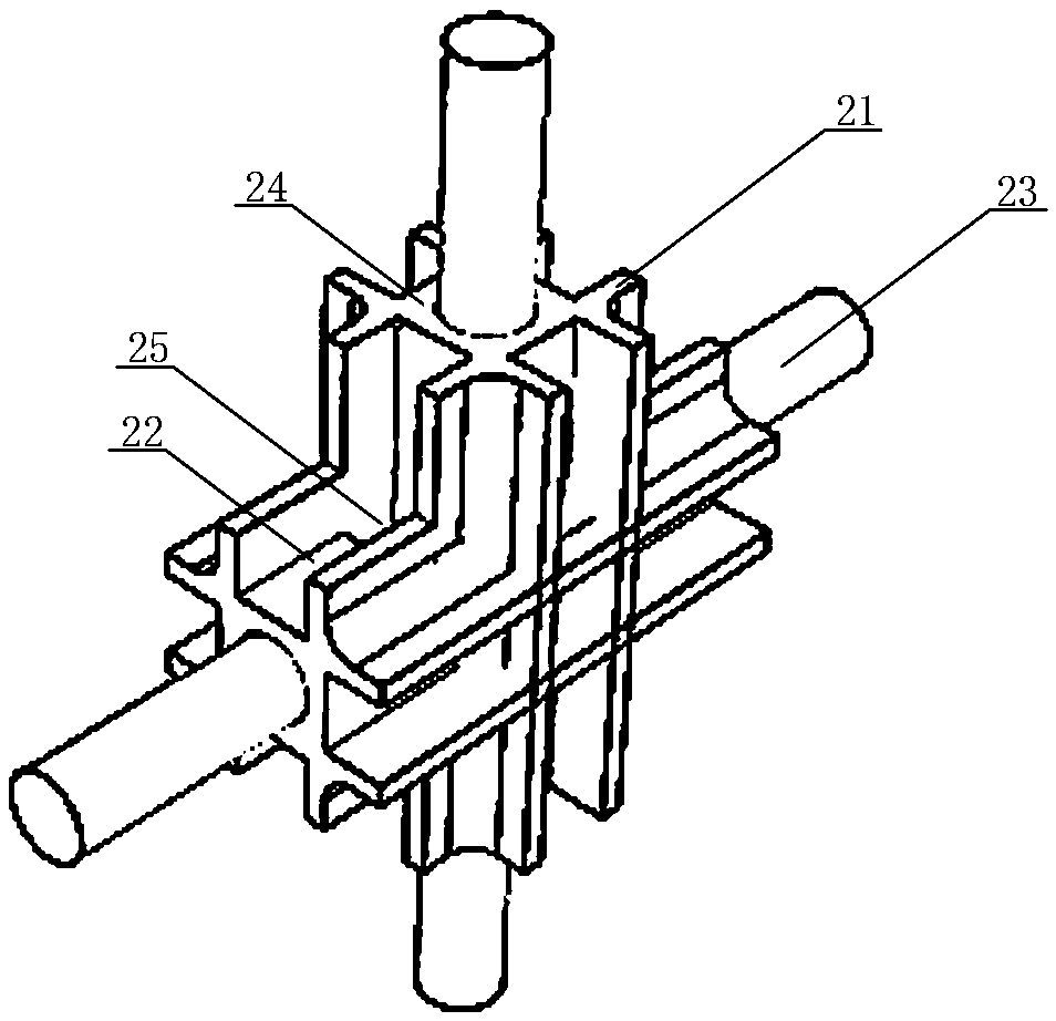
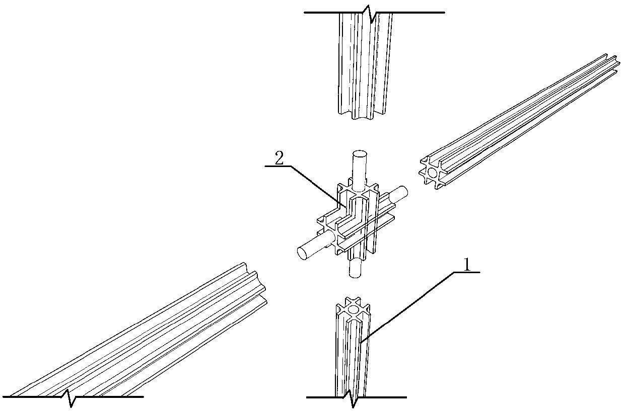
[0043] Embodiment one sees figure 1 As shown, the sealing strip for pressing and guiding flow is a bar-shaped piece whose cross-section is well-shaped, including a rectangular cylinder 14 in the middle and four pairs of clamping ribs 11 vertically distributed outward; each pair The retaining ribs and the sides of the rectangular cylinder form a guide groove 12; the inside of the rectangular cylinder 14 is provided with an insertion cavity 13.

[0044] The insertion cavity 13 is arranged at both ends of the rectangular cylindrical cylinder 14 or along the entire length of the central axis of the rectangular cylindrical cylinder, and its cross-sectional shape is circular, elliptical or polygonal.

[0045] The inner female angle formed by the fastening rib 11 and the side of the rectangular cylinder is a right angle or an arc chamfer.

[0046] The vulva angle formed by the fastening rib and another vertically adjacent fastening rib is a right angle or an arc chamfer.

[0047] D...

Embodiment 2

[0052] Embodiment two see Figure 9 As shown, different from the first embodiment, the outer end of the fastening rib 11 can also be cylindrical, and its diameter is greater than the thickness of the main body of the fastening rib, so as to enhance the sealing effect with the wallboard. The corresponding joint transition ribs are consistent with the clamping ribs.

[0053] see Figure 5 , Image 6As shown, a flow diversion sealing wall using the above-mentioned press-fit diversion sealing strip, the wall panel 3 includes a wall panel body 31 and U-shaped clamping parts arranged on the upper, lower, left, and right sides of the wall panel body 31. Groove 32; the sealing strip 1 is embedded in the fastening groove 32 of the wallboard 3; wherein the fastening rib on one side of the sealing strip 1 is embedded in the fastening groove, and the outer corner of the fastening rib fits on the fastening groove port The height of the fastening rib is adapted to the depth of the fasten...


PUM


Abstract

The invention relates to a pressure sticking flow-guiding sealing strip, a flow-guiding sealing wall and a construction method thereof. The sealing strip is a strip-shaped part. The cross section of the sealing strip is in a # shape. The sealing strip includes a middle rectangular column barrel, an insertion chamber is disposed in the rectangular column barrel, and four outer sides of a square barrel are provided with four pairs of clamping fixing ribs protruding vertically outwards. Flow guide grooves are formed in the side of each pair of clamping fixing rib and the rectangular column barrel. A main body of the sealing strip is in the # shape, the sealing strip is high in structural strength, elasticity and adaptability, the insertion chamber at the middle improves the strength and elasticity of the sealing strip, and at the same time conditions are also provided for the connection between the sealing strips. During wallboard construction, since the sealing strip is elastic, the clamping fixing rib is subjected to elastic deformation when clamped and installed with the wall, even if an error occurs in the interval between the wallboards, the sealing strip can also provide a certain deformation, the installation of the sealing strip is ensured, the construction quality is controllable, and the requirements for construction precision are not high, which is favorable for improving construction efficiency and construction quality. The pressure sticking flow-guiding sealing strip, the flow-guiding sealing wall and the construction method thereof can be widely used in structural system construction.

Description

technical field [0001] The invention relates to the field of building construction, in particular to a sealing structure system and a construction method thereof. Background technique [0002] At present, in structural construction, sealants, sealing rods and other components are mostly used for sealing between walls. However, under normal circumstances, the service life of sealants is significantly shorter than that of diversion sealed walls. Therefore, as the service life increases , the sealant often loses its sealing effect, causing water seepage in the wall; while traditional sealing rods and other components are an absolute sealing means, which cannot be adjusted, repaired, and have no adaptability; in addition, the existing sealing components cannot A unified combination is formed, each is independent and cannot be coordinated; finally, traditional sealing methods have relatively high requirements for construction, and once the construction is not in place, it is diff...

Claims


Application Information

Patent Timeline
Patent Type & Authority Patents(China)
IPC IPC(8): E04B1/684E04B2/00
CPCE04B1/6813E04B2/00
Inventor 朱宏宇侯建群
Owner ARCHITECTURAL DESIGN & RES INST OF TSINGHUA UNIV
Learn More