Electromagnetic switching valve and high-pressure fuel pump

An on-off valve, electromagnetic technology, applied in the field of fuel high-pressure pump, can solve problems such as weakening motion, and achieve the effect of reducing switching time

Active Publication Date: 2018-08-21
VTESCO TECH GMBH
View PDF2 Cites 2 Cited by
  • Summary
  • Abstract
  • Description
  • Claims
  • Application Information

AI Technical Summary

Problems solved by technology

But it is difficult to dampen the movement in

Method used


Image

  • Electromagnetic switching valve and high-pressure fuel pump
  • Electromagnetic switching valve and high-pressure fuel pump
  • Electromagnetic switching valve and high-pressure fuel pump

Examples


Embodiment Construction

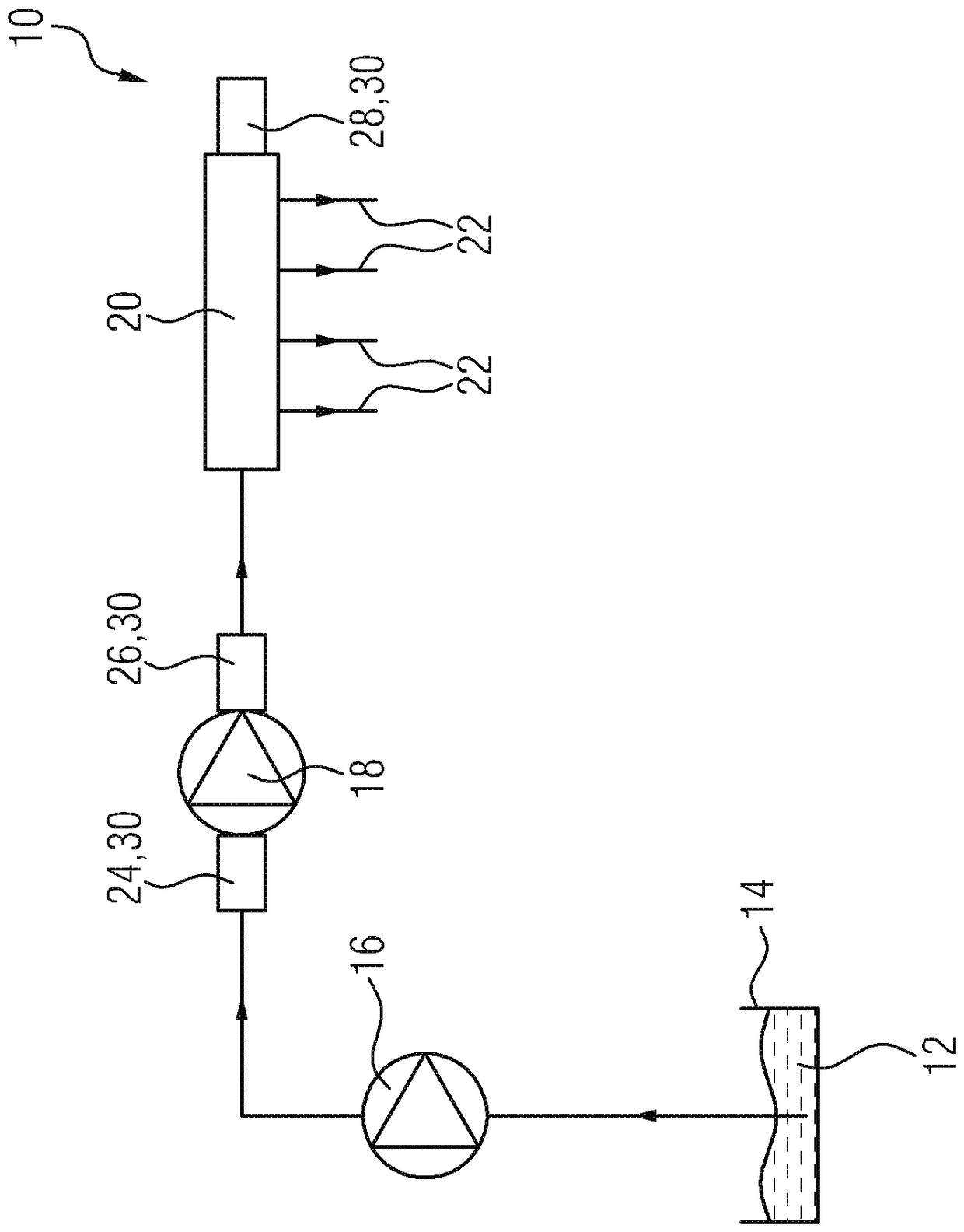
[0041] figure 1A schematic overview of a fuel injection system 10 of an internal combustion engine is shown, which delivers fuel 12 from a tank 14 to injectors 22 via a prefeed pump 16 , a high-pressure fuel pump 18 and a high-pressure fuel accumulator 20 , the injector then injects fuel 12 into the combustion chamber of the internal combustion engine.

[0042] The fuel 12 is introduced into the high-pressure fuel pump 18 via an inlet valve 24 , is discharged from the high-pressure fuel pump 18 via an outlet valve 26 under pressure, and is then conveyed to the fuel high pressure accumulator 20 . A pressure regulating valve 28 is arranged on the high-pressure fuel accumulator 20 in order to be able to regulate the pressure of the fuel 12 in the high-pressure fuel accumulator 20 .

[0043] Both the inlet valve 24 and the outlet valve 26 as well as the pressure regulating valve 28 can be designed as electromagnetic switching valves 30 and can therefore be actively operated.

...


PUM


Abstract

The invention relates to an electromagnetic switching valve (30) for a fuel injection system (10) of an internal combustion engine having an actuator region (38) for moving a closing element (48) witha pole piece (40) and an armature (44) and a solenoid (52) Generating a magnetic flux in the armature (44) and pole piece (40), wherein the armature (44) has a magnetic flux concentration region (66).

Description

technical field [0001] The invention relates to an electromagnetic switching valve for a fuel injection system of an internal combustion engine and to a high-pressure fuel pump having such an electromagnetic switching valve. Background technique [0002] The fuel high-pressure pump in the fuel injection system in the internal combustion engine is used to apply high pressure to the fuel, wherein the pressure is, for example, in the range of 150 bar to 400 bar for gasoline internal combustion engines and in the range of 1500 bar to 2500 bar for diesel internal combustion engines within range. The higher the pressure that can be generated in the corresponding fuel, the lower the emissions that are produced during the combustion of the fuel in the combustion chamber, which is advantageous especially against the background of the increasingly strong desire to reduce emissions. [0003] In the fuel injection system, valve means can be provided at different positions on the path o...

Claims


Application Information

Patent Timeline
IPC IPC(8): F02M51/06F02D41/38
CPCF02D41/3809F02M51/0614F02M51/0664F02M51/0628F02M59/366F02M2200/08F02M51/061F02M59/466F02M63/0015F02B2275/14F02M51/0682F02M59/368F02M63/0022F02M2200/09H01F7/08
Inventor M.布勒克B.古格尔A.米尔鲍尔H.迈斯盖尔
Owner VTESCO TECH GMBH
Why Eureka
Try Eureka