
Method used for calculating cutting process strain rate based on grid flow difference

A cutting process and strain rate technology, used in the analysis of materials, testing machinability, instruments, etc., can solve problems such as limiting the understanding of the cutting process and high cutting speed.

Inactive Publication Date: 2018-08-21
SHANDONG UNIV
View PDF4 Cites 0 Cited by
  • Summary
  • Abstract
  • Description
  • Claims
  • Application Information

AI Technical Summary

Problems solved by technology

[0004] High-speed cutting has been widely studied due to its many advantages, but the high cutting speed also limits the understanding of the cutting process

Method used


Image

  • Method used for calculating cutting process strain rate based on grid flow difference
  • Method used for calculating cutting process strain rate based on grid flow difference
  • Method used for calculating cutting process strain rate based on grid flow difference

Examples


Embodiment

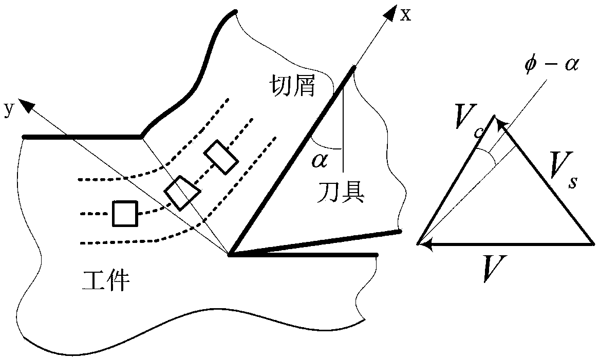
[0055] Such as figure 1 As shown, the grid of nanoscale size is processed by femtosecond laser, the angle of tool rake angle α and the angle of shear angle φ are measured, and the cutting speed V is measured;

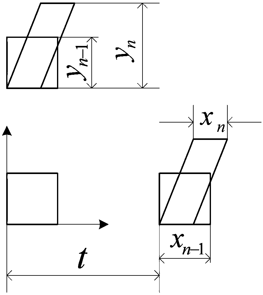
[0056] Such as figure 2 As shown, the grid in a certain area starts from the initial slip line, and after a period of time t slips, it crosses the shear plane and deforms at the same time. After measuring the lengths of xn-1 and xn, that is, measuring the lengths of two adjacent grids The length of the grid in the x direction, then the deformation of the grid in the x direction is:

[0057]

[0058] The elapsed time t is:

[0059]

[0060] Combining the two formulas (1) and (2), the strain rate distribution along the rake face direction is obtained as

[0061]

[0062] Similarly, the shear strain rate along the shear plane direction can be obtained

[0063]


PUM


Abstract

The invention discloses a method used for calculating cutting process strain rate based on grid flow difference. The method comprises following steps: the surface of a material to be measured is provided with grids via processing, from slip lines, grids of a certain area are subjected to slip for a certain period of time t, and deformation is caused with passing through a shearing plane, the length change of the grids at the certain period of time in the x direction is measured, and the deformation at the x direction is determined; time consumed in grid cutting deformation is determined basedon the moving distance of the grids along the x direction and the moving speed of cuttings along a front knife surface, and the strain rate distribution along the x direction is calculated; the abovesteps are repeated, and the cutting strain rate along the y direction is calculated. According to the method, shearing process is studied at the flowing angle, so that preferable study on the change rules of a plurality of physical parameters in cutting process is realized.

Description

technical field [0001] The invention relates to a method for calculating the strain rate in the cutting process based on the grid flow difference. Background technique [0002] Correctly describing the mechanical behavior of material deformation under different strain rates is the research content of solid mechanics. The cutting process of plastic materials is a large deformation process with high temperature and high strain rate. Correctly understand the change law of its strain rate and the strain rate The influence on other physical parameters is very important to understand the cutting process. However, the cutting speed and high temperature in the cutting process make the measurement and observation of the strain rate very inconvenient. [0003] Metal materials will undergo permanent deformation when the applied load exceeds the yield limit. Usually, the flow stress is used to characterize the macroscopic deformation resistance of the material when it undergoes plastic ...

Claims


Application Information

Patent Timeline
IPC IPC(8): G01N3/58
CPCG01N3/58G01N2203/0025G01N2203/0053G01N2203/0298G01N2203/0688
Inventor 张克国徐晓东
Owner SHANDONG UNIV
Learn More