
Two-path parallel connection-based two-phase type wireless electric energy transmission device

A technology of wireless power transmission and parallel connection, applied in the direction of circuit devices, electrical components, etc., can solve problems such as large output DC ripple coefficient, control circuit does not have phase shift control function, and transmission power capacity limitation, etc., to reduce ripple The effect of wave coefficient, DC component increase, and transmission power increase

Inactive Publication Date: 2018-08-21
QINGDAO UNIV OF SCI & TECH
View PDF3 Cites 6 Cited by
  • Summary
  • Abstract
  • Description
  • Claims
  • Application Information

AI Technical Summary

Problems solved by technology

The existing single-channel wireless transmission system only uses single-phase rectification, the control circuit does not have the function of phase-shift control, and only single-phase AC power is transmitted to the secondary side. There is a large output DC ripple coefficient, and the ability to transmit power is completely affected by components. Disadvantages such as capacity limitations

Method used


Image

  • Two-path parallel connection-based two-phase type wireless electric energy transmission device
  • Two-path parallel connection-based two-phase type wireless electric energy transmission device
  • Two-path parallel connection-based two-phase type wireless electric energy transmission device

Examples


Embodiment Construction

[0025] In order to understand the above-mentioned purpose, features and advantages of the present invention more clearly, the present invention will be further described below in conjunction with the accompanying drawings and embodiments. It should be noted that, in the case of no conflict, the embodiments of the present application and the features in the embodiments can be combined with each other.

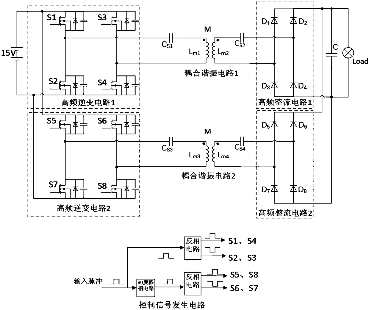
[0026] Such as figure 1 As shown, a two-phase parallel wireless power transmission device includes a 15V power supply, a load, a first wireless power transmission circuit and a second wireless power transmission circuit, and a control signal generation circuit; the first wireless power transmission circuit It is connected in parallel with the second wireless power transmission circuit, and its two ends are respectively connected to the power supply and the load; the control signal generation circuit is connected to the input pulse to generate two pairs of pulse control signals w...


PUM


Abstract

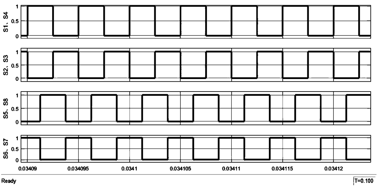
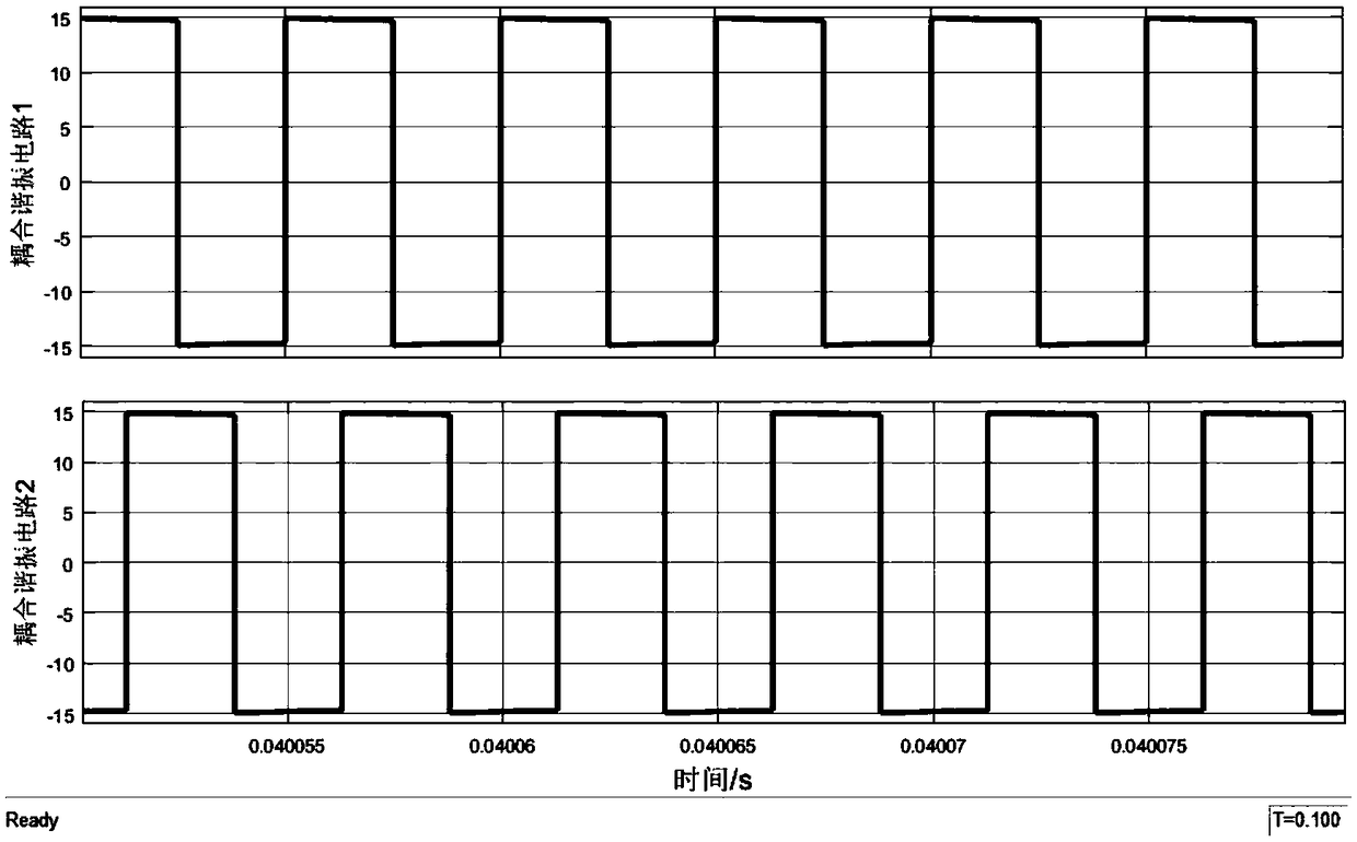
The invention discloses a two-path parallel connection-based two-phase type wireless electric energy transmission device. The device comprises a power source, a load, a first wireless electric energytransmission circuit, a second wireless electric energy transmission circuit, and a control signal generation circuit; the first wireless electric energy transmission circuit and the second wireless electric energy transmission circuit are connected in parallel; and the control signal generation circuit is used for generating two pairs of pulse control signals with a phase difference of 90 degrees, wherein the two pairs of pulse control signals are respectively applied to the control ends of the first wireless electric energy transmission circuit and the second wireless electric energy transmission circuit. According to the two-path parallel connection-based two-phase type wireless electric energy transmission device of the invention, a novel circuit structure design is adopted, a two-pathparallel connection transmission topological structure is adopted to decrease the current burden of a single path; the ripples of the output direct-current voltages of two paths can be weakened by each other by means of phase shift control, so that the ripple coefficients of the direct-current output voltages can be reduced; and the current transmission capability of the device can be greatly improved under the premise of identical single-path transmission capability, and power obtained by the load can be improved. The two-path parallel connection-based two-phase type wireless electric energytransmission device has high popularization value and practical value.

Description

technical field [0001] The invention relates to the field of wireless power transmission, in particular to a two-phase parallel wireless power transmission device. Background technique [0002] Wireless power transmission technology mostly involves single-channel transmission mode in the field of engineering application, and rarely involves multi-channel parallel transmission mode. The existing single-channel wireless transmission system only uses single-phase rectification, the control circuit does not have the function of phase-shift control, and only single-phase AC power is transmitted to the secondary side. There is a large output DC ripple coefficient, and the ability to transmit power is completely affected by components. Disadvantages such as capacity limitations. Contents of the invention [0003] The technical problem to be solved by the present invention is to provide a two-way parallel two-phase wireless power transmission device with dual-way energy transmiss...

Claims


Application Information

Patent Timeline
IPC IPC(8): H02J50/40H02J50/12
CPCH02J50/12H02J50/40
Inventor 逄海萍冷文鹏
Owner QINGDAO UNIV OF SCI & TECH
Learn More