A method of preparing natural gas at a gas pressure reduction stations to produce liquid natural gas (LNG)

A technology for liquid natural gas and natural gas, applied in gas fuel, gas processing, separation methods, etc., can solve problems such as high capital and operating costs

Active Publication Date: 2018-08-21
1304338 ALBERTA
View PDF5 Cites 0 Cited by
  • Summary
  • Abstract
  • Description
  • Claims
  • Application Information

AI Technical Summary

Problems solved by technology

Molecular sieves are a proven commercial approach, but they are expensive in capital and operating costs

Method used


Image

  • A method of preparing natural gas at a gas pressure reduction stations to produce liquid natural gas (LNG)
  • A method of preparing natural gas at a gas pressure reduction stations to produce liquid natural gas (LNG)
  • A method of preparing natural gas at a gas pressure reduction stations to produce liquid natural gas (LNG)

Examples


Embodiment Construction

[0063] DETAILED DESCRIPTION OF THE PREFERRED EMBODIMENT

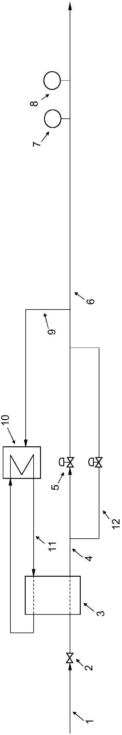
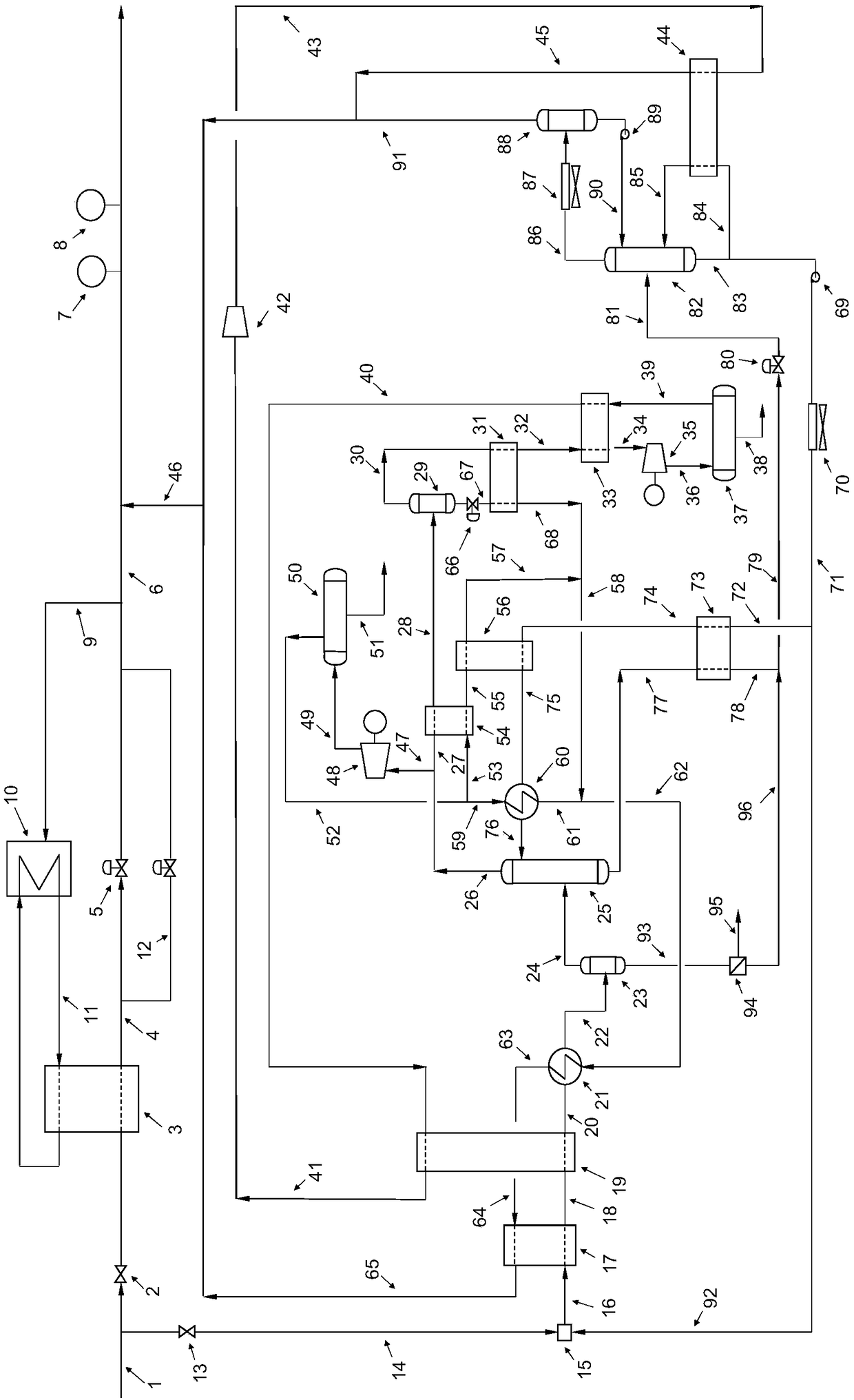
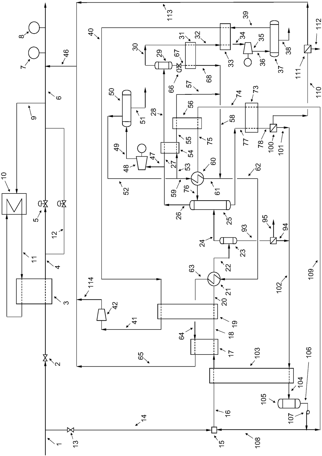
[0064] will now refer to Figures 1 to 3 Describe the method.

[0065] In the method of the present invention, cooling energy is provided by recovering pressure energy that is currently wasted in the depressurization station. The recovered energy also allows the methanol to be refrigerated at much cooler temperatures and thus with greater efficiency. For example, in the process of the present invention, the average refrigerated methanol temperature is -80°C.

[0066] The process was developed to prepare a natural gas stream at a gas decompression station for the production of LNG. Said method uses a different way of methane expansion cycle, which has heretofore been used in commercial applications known as decompression stations. The system described herein utilizes the gas flow delivered to the zone distribution pipeline at the depressurization station to provide an improved method of producing LNG at the depressur...


PUM


Abstract

A method to pre-treat an inlet natural gas stream at gas pressure reduction stations to produce LNG removes water and carbon dioxide from a natural gas stream. The energy required for the process is provided by recovering pressure energy in the inlet gas stream. The process eliminates the conventional gas pre-heating process at pressure reductions stations employing gas combustion heaters. The process provides a method to produce LNG at natural gas pressure reduction that meets product specifications.

Description

technical field [0001] The present invention relates to a process for the preparation of natural gas for the production of LNG at a gas decompression station by recovering the pressure drop from a transfer line to a distribution line. The recovered pressure energy is converted into electricity and refrigeration to prepare and produce LNG. [0002] In one example, to prepare natural gas for the production of LNG, the water and carbon dioxide content of the natural gas stream is reduced to meet LNG product specifications, and the methanol stream is conditioned at a pressure reduction station with recovered gas pressure energy for use from natural gas Water and carbon dioxide are removed from the stream. Background technique [0003] The pressure relief station is located along the high pressure natural gas main delivery pipeline used to distribute the gas to the regional pipeline. The purpose of the pressure reducing station is to control the flow and pressure of natural gas...

Claims


Application Information

Patent Timeline
Patent Type & Authority Applications(China)
IPC IPC(8): C10L3/10
CPCC10L3/10B01D53/1475B01D2252/2021B01D2257/502B01D2257/80C10L2290/545F25J3/0209F25J3/0233F25J3/0238F25J2200/02F25J2200/78F25J2205/04F25J2205/40F25J2205/50F25J2210/06F25J2215/04F25J2220/66F25J2220/68F25J2230/30F25J2240/02F25J2240/30F25J2270/04F25J2270/08F25J2270/88F25J2290/60B01D53/1425C10L3/104Y02C20/40
Inventor J·洛伦索M·米利亚尔
Owner 1304338 ALBERTA
Why Eureka
Try Eureka