
Welding method of electric resistance welding

A welding method and resistance welding technology, applied in the field of resistance welding, can solve the problems of unable to achieve surface-to-surface sealing welding, unable to guarantee surface-to-surface sealing welding, etc.

Active Publication Date: 2018-08-24
佛山市智晓科技服务有限公司
View PDF7 Cites 2 Cited by
  • Summary
  • Abstract
  • Description
  • Claims
  • Application Information

AI Technical Summary

Problems solved by technology

When surface-to-surface sealing welding is required, if there is no special processing on the surface, when the two surfaces are in direct contact (even with a certain roughness), pre-press the two surfaces to make them contact before welding, and the length L at this time is almost 0 (the tiny bumps of roughness can be almost ignored), the contact area S can be understood as extremely large, then the resistance R is infinitely small at this time, and the current I needs to be infinitely large to generate enough heat to melt the metal, which is exactly It is the reason why the current resistance welding equipment on the market cannot achieve surface-to-surface sealing welding
[0006] Moreover, the current welding process only needs to consider the connection of the nugget position during the pressure application process, and does not need to consider the connection of the position outside the nugget, which also makes it impossible for the nugget to form a uniform filling outside the nugget, that is, outside the nugget The position is usually not filled by molten metal, so that there are a lot of gaps in other positions except the nugget position, and it is impossible to ensure the sealing welding of the surface to the surface

Method used


Image

  • Welding method of electric resistance welding
  • Welding method of electric resistance welding
  • Welding method of electric resistance welding

Examples


Embodiment 1

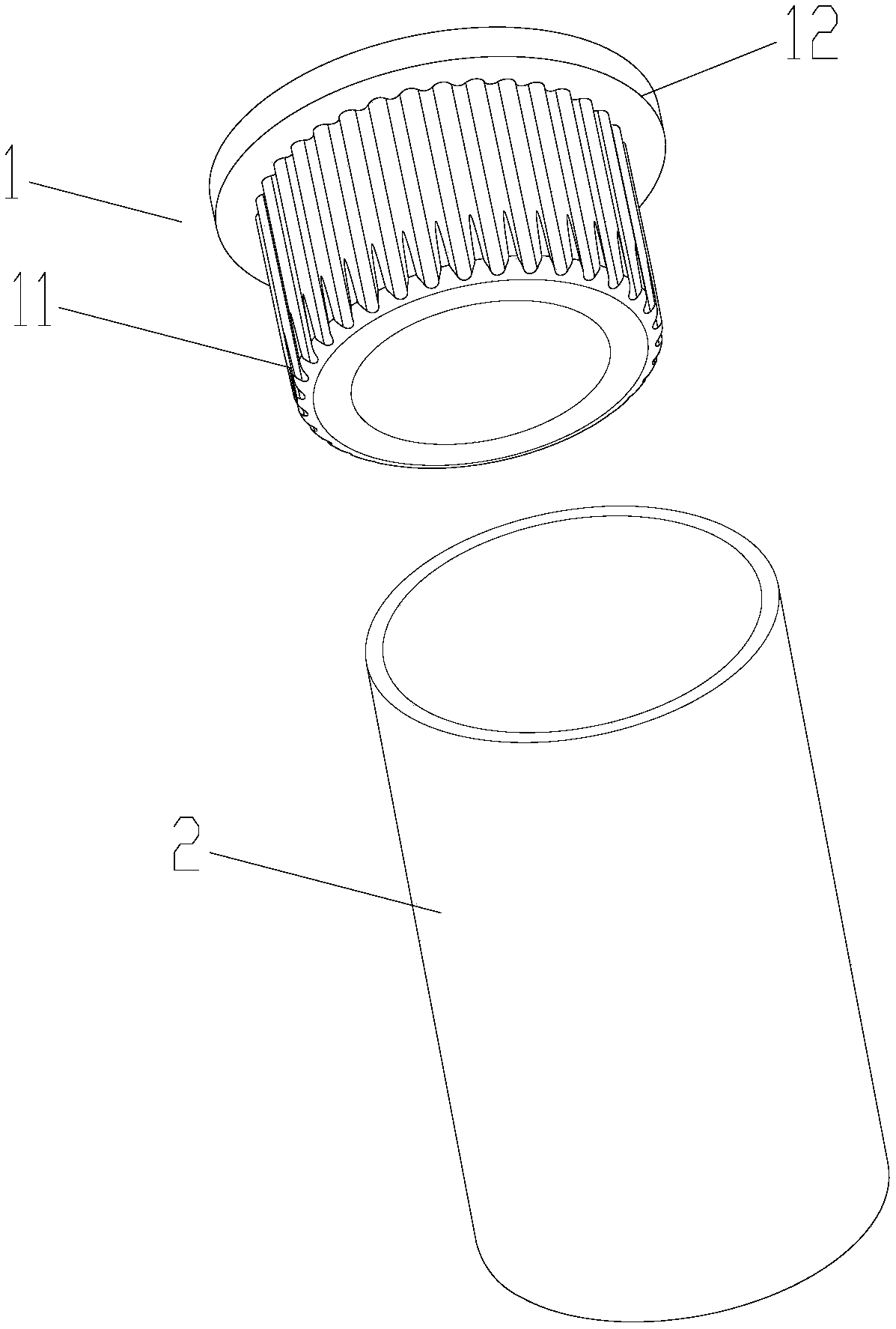
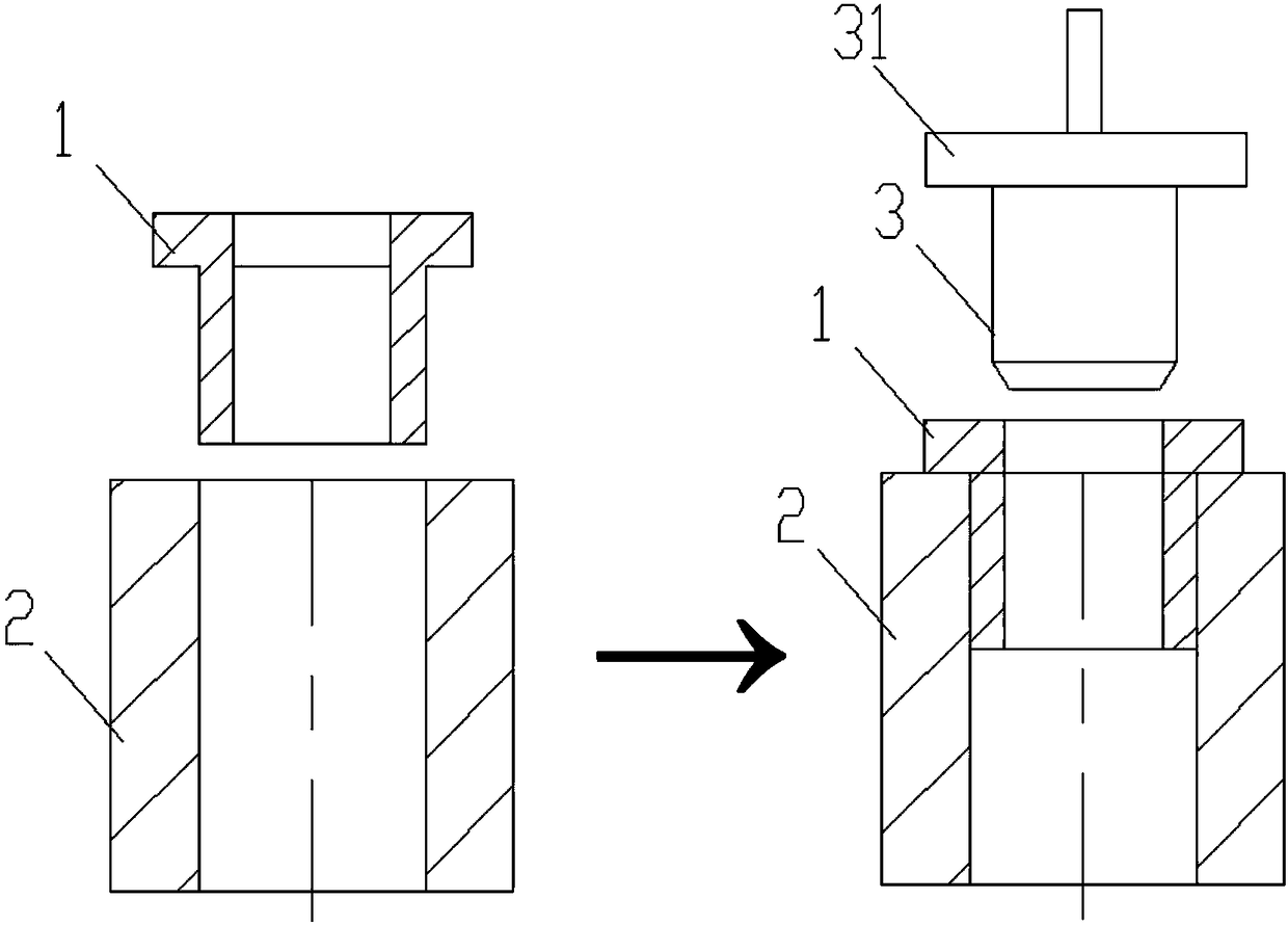
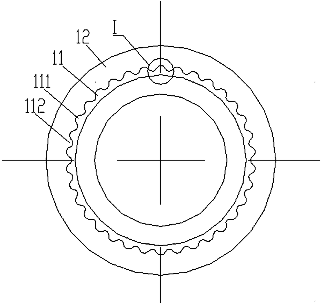
[0038] Such as Figure 1-Figure 4 , In this embodiment, in this embodiment, the metal pipe fitting 2 is an iron or stainless steel pipe, and the metal pipe fitting 1 is a copper pipe and is provided with a surface treatment portion 11 on its outer surface (because copper is soft and has a low melting point). The surface treatment part 11 is a plurality of vertical linear grooves and thus has a structure of a plurality of protrusions 111 and depressions 112 . In this embodiment, the height H of the protrusion 111 is 0.4 mm, the distance P between the vertical linear grooves is 1 mm, and the arc radius of the top of the protrusion is 0.4 mm. In the cross-section of the surface treatment part 11 , the protrusions 111 and the depressions 112 are regularly arranged alternately. Most preferably, as in this embodiment, the cross-sections of the protrusions 111 and the depressions 112 are sinusoidal.

[0039] The two metal pipe fittings 1 and 2 are interference fit, and the surfaces ...

Embodiment 2

[0043] Such as Figure 5-Figure 6 As shown, in this embodiment, the top of the metal pipe fitting 1 does not need to be provided with a flange, but a limiting step 21 is provided on the inner wall of the metal pipe fitting 2 to play a role of limiting. The metal pipe fitting 2 is an iron or stainless steel pipe, and the metal pipe fitting 1 is a copper pipe and has a surface treatment part 11 on its outer surface. The surface treatment part 11 is a textured knurled surface, and the grid is rhombus.

[0044] Others are the same as embodiment 1.

Embodiment 3

[0046] Such as Figure 7-Figure 9 As shown, in this embodiment, the top of the metal pipe fitting 1 does not need to be provided with a flange, but a limiting step 21 is provided on the inner wall of the metal pipe fitting 2 to play a role of limiting. The metal pipe fitting 2 is an iron or stainless steel pipe, and the metal pipe fitting 1 is a copper pipe with a surface treatment part 11 on its outer surface. In this embodiment, the height H of the protrusion 111 is 0.3 mm, the distance P between the vertical line grooves is 0.6 mm, and the arc radius of the top of the protrusion is 0.3 mm. In the longitudinal section of the surface treatment part 11 , the protrusions 111 and the depressions 112 are regularly and alternately arranged. Most preferably, as in this embodiment, the cross-sections of the protrusions 111 and the depressions 112 are sinusoidal.

[0047] The two metal pipe fittings 1 and 2 are clearance fit. After the two are socketed, the pressure of outward expan...


PUM

PropertyMeasurementUnit
Bump heightaaaaaaaaaa
Widthaaaaaaaaaa
Arc radiusaaaaaaaaaa

Abstract

The invention discloses a welding method of electric resistance welding. The method comprises at least two metal pipe fittings to be welded, and at least one surface of the to-be-welded surface of themetal pipe fittings is provided with a surface treatment part, the surface treatment part is of a structure with a plurality of protrusions and recesses; and in welding, the protrusions are melted byelectrifying, and then pressure is applied to enable the protrusions melted metal to be squeezed and migrated to the positions of recesses until the migrated protrusions molted metal volume is largerthan or equal to the amount of space required to be filled up by the recesses, and the to-be-welded surface is sealed and welded. According to the electric resistance welding, the metal workpiece tobe welded is pre-machined, the to-be-welded surface is provided with the plurality of protrusions, when electrified welding is carried out, the resistance of protrusion parts reaches the maximum, namely the heating volume is the largest, and the metal of the protrusion parts reaches the softening state firstly; the pressure is applied at the moment, so that the protrusion parts can be deformed tobe filled with the parts which are sunken to the periphery, and the temperature of the protrusion parts is further increased due to the fact that current is further conducted, and the melted metal isfinally enabled the to-be-welded surface of the metal workpiece to be well combined.

Description

technical field [0001] The invention relates to the field of welding, in particular to a resistance welding method. Background technique [0002] In products in various fields, it is often necessary to use connecting pipes, and the materials of the parts connected at both ends of the connecting pipes are usually different. Taking the exhaust pipe and suction pipe of the compressor in the current prior art as an example, most of them are made of copper, one end is welded with other copper pipes, and the other end is brazed with the iron of the compressor by silver solder flame. Cover or iron shell connection. When flame brazing is used, the copper tube is generally embedded in the iron upper cover or iron shell, and the solder is heated and melted by the flame to fill the gap between the copper tube and the iron material, so that the copper tube and the iron tube can be filled in Solder in the gap joins the three together. When welding, the welding temperature is higher th...

Claims


Application Information

Patent Timeline
IPC IPC(8): B23K11/00B23K11/36B23K11/14
CPCB23K11/00B23K11/14B23K11/36
Inventor 温爱春
Owner 佛山市智晓科技服务有限公司
Learn More