Energy-saving tempering furnace

A tempering furnace and furnace body technology, applied in furnaces, heat treatment furnaces, furnace types, etc., can solve the problems of low heat utilization rate, troublesome installation and removal of workpieces, large energy consumption of tempering furnaces, etc., to achieve uniform heating, convenient removal operation, Guaranteed efficiency

Inactive Publication Date: 2018-08-24
浙江宇辰工业炉有限公司
View PDF1 Cites 0 Cited by
  • Summary
  • Abstract
  • Description
  • Claims
  • Application Information

AI Technical Summary

Problems solved by technology

However, most of the existing tempering furnaces consume a lot of energy and have low heat utilization rates.
[0003] The patent document whose notification number is CN206418160U discloses a kind of energy-saving tempering furnace, which includes a furnace body. A furnace cavity is arranged inside the furnace body. A furnace door is installed at the front end of the furnace body. The plate is fixed on the inner wall of the rear end of the furnace body, and an air duct is left between the baffle plate and the side wall of the

Method used


Image

  • Energy-saving tempering furnace
  • Energy-saving tempering furnace
  • Energy-saving tempering furnace

Examples


Embodiment Construction

[0022] The following will clearly and completely describe the technical solutions in the embodiments of the present invention with reference to the accompanying drawings in the embodiments of the present invention. Obviously, the described embodiments are only some, not all, embodiments of the present invention.

[0023] In describing the present invention, it should be understood that the terms "center", "longitudinal", "transverse", "length", "width", "thickness", "upper", "lower", "front", " Orientation indicated by rear, left, right, vertical, horizontal, top, bottom, inside, outside, clockwise, counterclockwise, etc. The positional relationship is based on the orientation or positional relationship shown in the drawings, and is only for the convenience of describing the present invention and simplifying the description, rather than indicating or implying that the referred device or element must have a specific orientation, be constructed and operated in a specific orientat...


PUM


Abstract

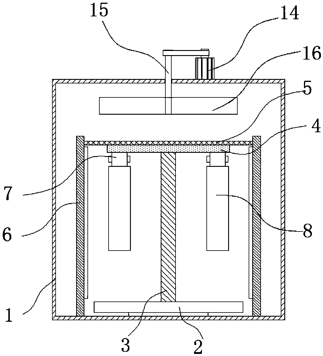
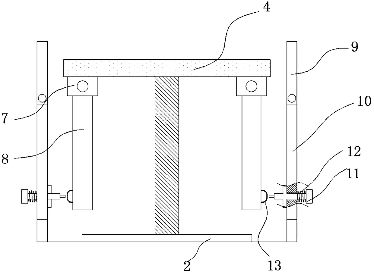
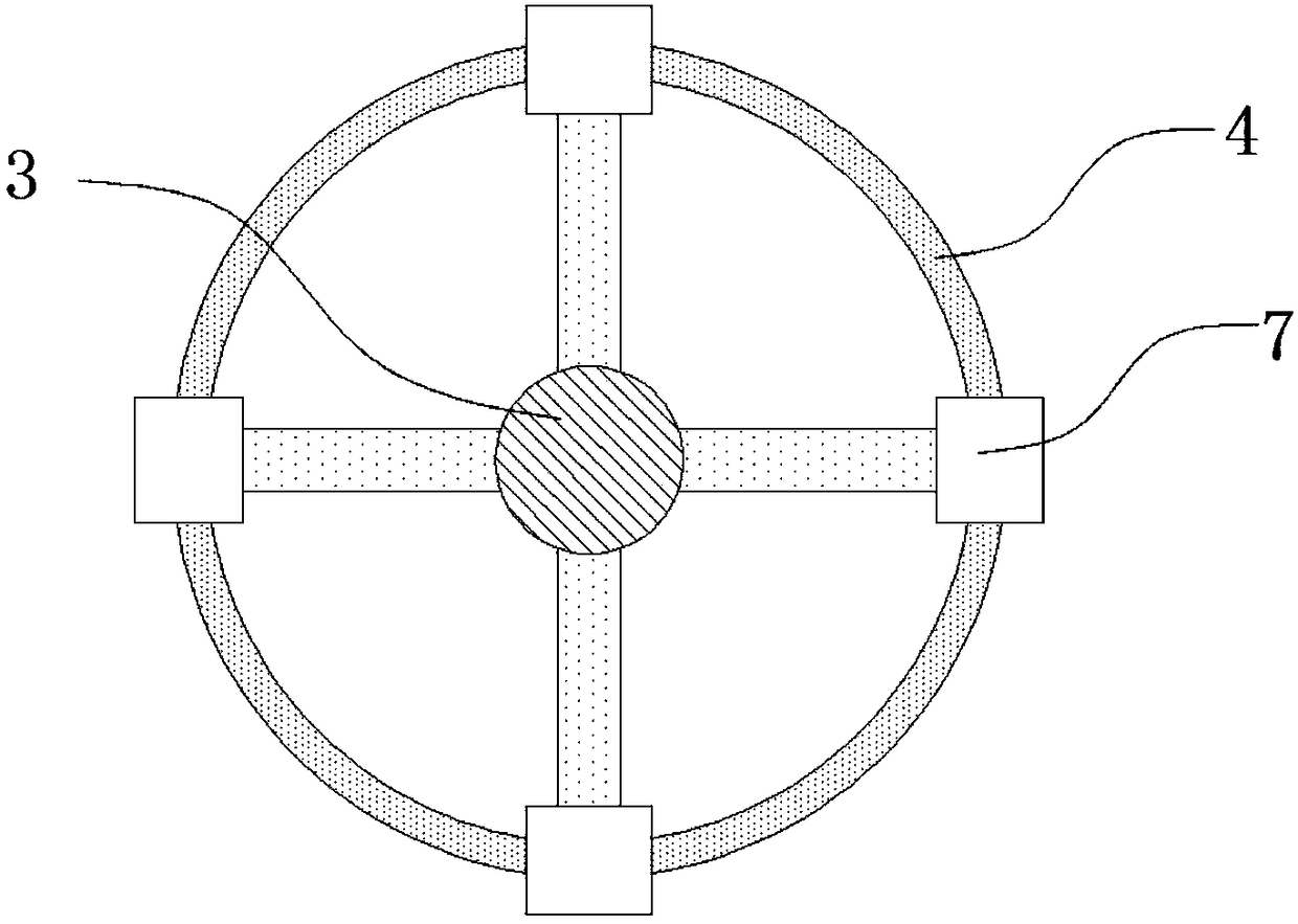
The invention discloses an energy-saving tempering furnace. The energy-saving tempering furnace comprises a furnace body; a turntable is arranged on the inner wall of the bottom of the furnace body; avertical support shaft is arranged in the center of the turntable; a rotating ring is arranged at the top of the support shaft; vertical baffle plates are arranged on the inner wall of the bottom ofthe furnace body; the baffle plates are positioned on the left side and the right side of the turntable; a horizontal fence plate is arranged between the baffle plates; the rotating ring is mounted atthe bottom of the fence plate through a bearing; the bottom of the rotating ring is connected with four sets of identical mounting bases through screws; the bottom of a mounting base is hinged with abracket; parts to be machined are placed in the bracket; furnace doors are prearranged on the front side and the back side of the furnace body, and are provided with through port grooves; and flashboards are mounted in the through port grooves through hinges. The energy-saving tempering furnace can guarantee uniform heating of the machined parts inside, can recycle heat to achieve the energy saving effect, and meanwhile, is convenient for staff to take out the parts to guarantee the production efficiency.

Description

technical field [0001] The invention relates to the technical field of tempering furnaces, in particular to an energy-saving tempering furnace. Background technique [0002] The tempering furnace is used for tempering general metal parts in air and quenching, annealing and aging heat treatment for aluminum alloy die-casting parts, pistons, aluminum plates and other light alloy parts. In the process of automobile manufacturing, many spare parts need to be quenched, annealed, and aging heat treated in a tempering furnace. However, most of the existing tempering furnaces consume a lot of energy and have low heat utilization rates. [0003] The patent document whose notification number is CN206418160U discloses a kind of energy-saving tempering furnace, which includes a furnace body. A furnace cavity is arranged inside the furnace body. A furnace door is installed at the front end of the furnace body. The plate is fixed on the inner wall of the rear end of the furnace body, an...

Claims


Application Information

Patent Timeline
IPC IPC(8): C21D9/00
CPCC21D9/00
Inventor 刘世华
Owner 浙江宇辰工业炉有限公司
Why Eureka
Try Eureka