Lifting and rotating device and 3D house printer

A technology of lifting, rotating, and rotating components, which is applied in construction, building construction, and building material processing. It can solve the problems of limited printing range and cumbersome operation, and achieve the effects of improving utilization, simplifying steps, and improving efficiency.

Pending Publication Date: 2018-08-24
天津依蓝时代电气设备有限公司
View PDF0 Cites 2 Cited by
  • Summary
  • Abstract
  • Description
  • Claims
  • Application Information

AI Technical Summary

Problems solved by technology

[0006] The purpose of the present invention is to provide a 3D house printer, which is used to solve the problems of limited printing range, inability to meet the needs of different construction requirements, and the need to move the whole device when another direction is required, cumbersome operation, etc.

Method used


Image

  • Lifting and rotating device and 3D house printer
  • Lifting and rotating device and 3D house printer
  • Lifting and rotating device and 3D house printer

Examples


Embodiment 1

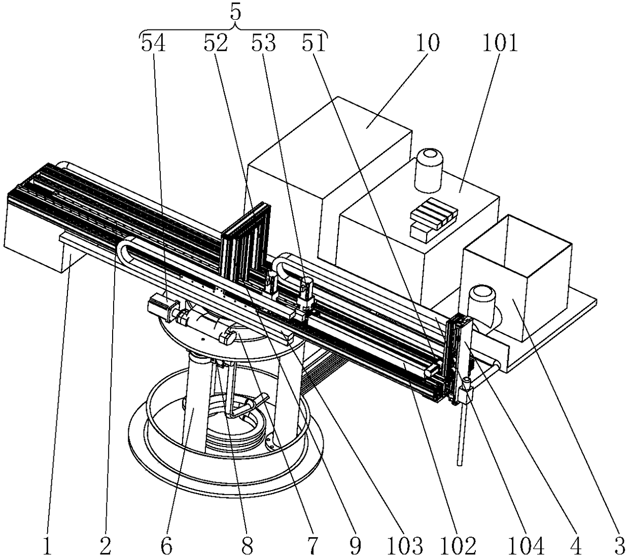
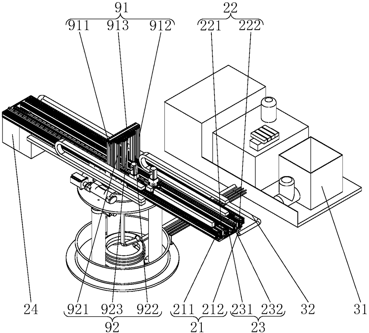
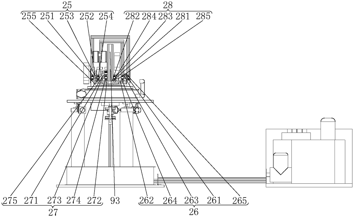
[0062] Such as Figure 1 to Figure 10 As shown, it includes a first driving member 54, a rotating assembly 7, a lifting assembly 6 and a walking assembly;

[0063] The first driving member 54 is connected with the rotating assembly 7;

[0064] The truss assembly 2 is arranged on the rotating assembly 7, and the rotating assembly 7 is used to drive the truss assembly 2 to rotate;

[0065] The lifting assembly 6 is arranged below the rotating assembly 7 for supporting the rotating assembly 7 and driving the rotating assembly 7 up and down;

[0066] The walking assembly is arranged below the lifting assembly 6 for driving the lifting assembly 6 and the rotating assembly 7 to move.

[0067] The lifting and rotating device includes a first driving member 54, a rotating assembly 7, a lifting assembly 6 and a walking assembly, the first driving member 54 is connected with the rotating assembly 7, and the rotating assembly 7 is provided with a truss assembly 2, and the rotating asse...

Embodiment 2

[0089] Such as Figure 1 to Figure 10 As shown, a 3D house printer provided in this embodiment includes the lifting and rotating device provided in Embodiment 1, and also includes a control assembly 1 and a truss assembly 2 connected to the control assembly 1, a feeding assembly 3, and a discharging assembly 4 and drive assembly 5;

[0090] The feeding assembly 3 is connected with the discharging assembly 4 for conveying building materials to the discharging assembly 4;

[0091] The discharge assembly 4 is arranged at one end of the truss assembly 2 for unloading when printing a house;

[0092] The driving assembly 5 is respectively connected with the truss assembly 2, the discharging assembly 4, the lifting assembly 6 and the rotating assembly 7, and is used to respectively drive the movement of the truss assembly 2, the discharging assembly 4, the lifting assembly 6 and the rotating assembly 7;

[0093] The lifting assembly 6 is arranged below the truss assembly 2 for adjust...

Embodiment 3

[0205] Different from Embodiment 2, the lifting component 6 adopts a tower crane.

[0206] Further, the number of tower cranes may be one, which is set at the center of the base 64 and connected with the center of the rotating assembly 7 .

[0207] Further, there may be multiple tower cranes, which are evenly spaced at the center of the base 64 and connected with the rotating assembly 7 .

[0208] In this city, using a tower crane as the lifting component 6 of the device can complete the construction of houses with higher height requirements.


PUM


Abstract

The invention discloses a lifting and rotating device and a 3D house printer. The lifting and rotating device and the 3D house printer comprises a first driving part, a rotating assembly, a lifting assembly and a walking assembly. The first driving part is connected with the rotating assembly. A truss assembly is arranged on the rotating assembly. The rotating assembly is used for driving the truss assembly to rotate. The lifting assembly is arranged under the rotating assembly, and the lifting assembly is used for supporting the rotating assembly and driving the rotating assembly to lift andlower. The walking assembly is arranged under the lifting assembly, and the walking assembly is used for driving the lifting assembly and the rotating assembly to rotate. Rotating and lifting and lowering of the truss assembly are completed by the lifting assembly and the rotating assembly. Compared with an existing gantry frame structure, only the rotating and lifting of the truss assembly is needed, and the whole equipment is not moved, so that steps of building house is simplified, the efficiency is improved, and at the same time, needs of different house building are met.

Description

technical field [0001] The invention relates to the technical field of house construction, in particular to a lifting and rotating device and a 3D house printer. Background technique [0002] Three-dimensional printing technology, also known as 3D (Three Dimensions) printing technology, is a technology based on digital models, using adhesive materials such as plastic or powdered metal, to construct objects by layer-by-layer printing. 3D printers appeared in the 1990s and are mechanical devices designed using 3D printing technology to construct objects of different forms. The working principle of a 3D printer is basically the same as that of an ordinary printer. The printer is filled with "printing materials" such as liquid or powder. After being connected to a computer, the "printing materials" are superimposed layer by layer through computer control, and finally the blueprint designed by the computer is printed into a physical object. In the process of realizing 3D printin...

Claims


Application Information

Patent Timeline
IPC IPC(8): E04G21/04
CPCE04G21/04
Inventor 李享
Owner 天津依蓝时代电气设备有限公司
Why Eureka
Try Eureka