Exhaust pipe

A technology for exhaust pipes and sliding sleeves, which is applied in the direction of exhaust devices, mechanical equipment, engine components, etc., which can solve the problems of easy adhesion of impurities in exhaust pipes, and achieve the effects of avoiding excessive moisture and enhancing the scraping effect

Active Publication Date: 2018-08-24
重庆市铭鼎机械制造有限公司
View PDF7 Cites 14 Cited by
  • Summary
  • Abstract
  • Description
  • Claims
  • Application Information

AI Technical Summary

Problems solved by technology

[0003] The invention discloses an exhaust pipe. The purpose of the invention is to solve th

Method used


Image

  • Exhaust pipe
  • Exhaust pipe
  • Exhaust pipe

Examples


Embodiment Construction

[0017] The following is further described in detail through specific implementation methods:

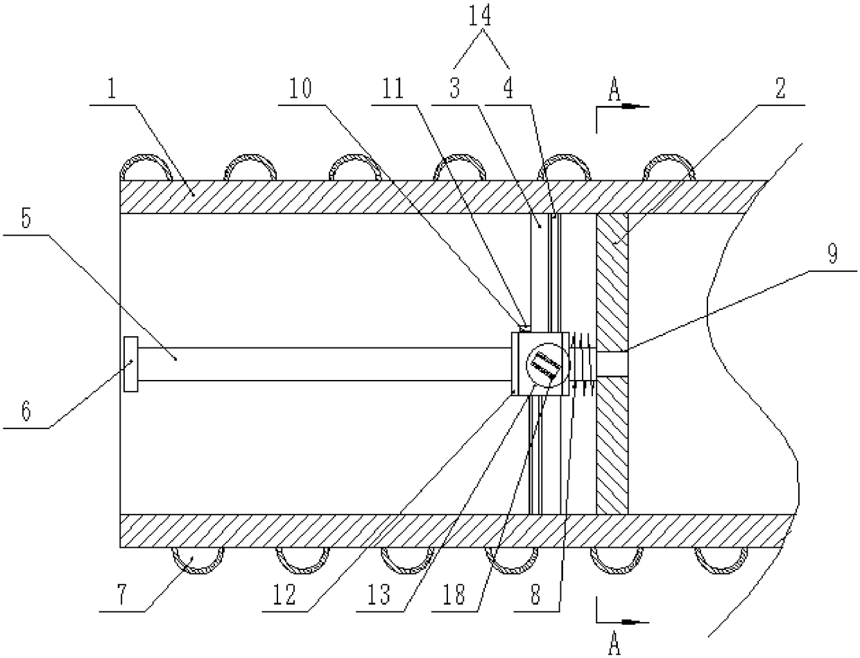
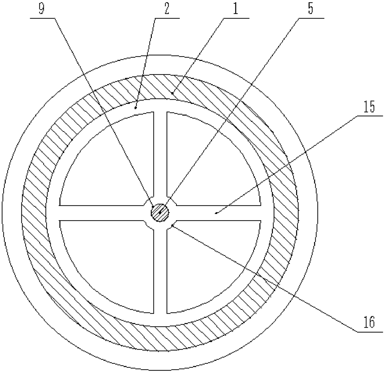
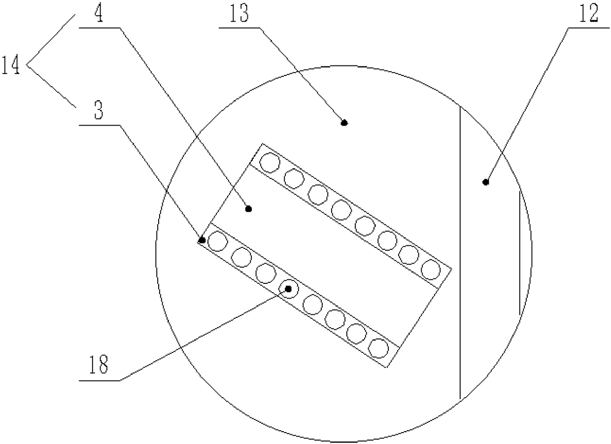
[0018] The reference signs in the drawings of the specification include: exhaust pipe 1, positioning bracket 2, splint 3, sponge layer 4, guide rod 5, limit boss 6, cooling pipe 7, tension spring 8, internal threaded hole 9, inlet Liquid port 10, sealing door 11, sliding sleeve 12, rotating sleeve 13, blade 14, positioning rod 15, positioning piece 16, liquid storage cavity 17, liquid outlet hole 18.

[0019] The embodiment is basically as figure 1 , figure 2 , image 3 and Figure 4 Shown: an exhaust pipe 1, including an exhaust pipe 1, an annular positioning bracket 2 is coaxially integrally formed in the exhaust pipe 1, and a positioning rod 15 in the shape of a "ten" is integrally formed on the inner wall of the positioning bracket 2 The intersection point of the positioning rod 15 is integrally formed with a circular positioning piece 16, the center of the positioning piece...


PUM


Abstract

The invention belongs to airflow silencers or exhaust devices of common machines or engines, and particularly discloses an exhaust pipe. The exhaust pipe comprises an exhaust pipe body. A positioningsupport is coaxially and fixedly connected to the inner wall of the exhaust pipe. A guiding rod is detachably connected to the positioning support. A sliding sleeve is slidably connected with the guiding rod. A rotary sleeve is coaxially and rotationally connected to an outer circle of the sliding sleeve. A blade is fixedly connected with the outer wall of the rotary sleeve. The free end of the blade abuts against the inner wall of the exhaust pipe body. The blade is provided with an adsorption mechanism for adsorbing moisture in waste gas. A cooling mechanism used cooling waste gas is arranged on the outer wall of the exhaust pipe body. A return mechanism used for driving the sliding sleeve to reciprocate on the guiding rod is arranged between the sliding sleeve and the positioning support. The problem that impurities are liable to attach to the inner walls of existing exhaust pipes is solved.

Description

technical field [0001] The invention belongs to an airflow muffler or an exhaust device of a general machine or engine, and specifically discloses an exhaust pipe. Background technique [0002] The exhaust pipe is a part of the exhaust system of the automobile engine. The exhaust pipe is used to discharge the gas produced by the engine combustion. Since the exhaust pipe is connected to the outside world, foreign impurities can easily enter the exhaust pipe and adhere to the exhaust pipe. At the same time When the engine combustion is not sufficient, the oil and gas cannot be completely combusted, resulting in carbon deposits. The carbon deposits are discharged through the exhaust pipe along with the exhaust gas generated by the combustion of the engine, so the carbon deposits are also discharged along the exhaust pipe along with the exhaust gas, but some carbon deposits It will adhere to the inner wall of the exhaust pipe. With the continuous adhesion of carbon deposits and ...

Claims


Application Information

Patent Timeline
IPC IPC(8): F01N3/04F01N5/04F01N13/08F01N13/18F01N13/00
CPCF01N3/043F01N5/04F01N13/00F01N13/08F01N13/1805Y02T10/12
Inventor 张序
Owner 重庆市铭鼎机械制造有限公司
Why Eureka
Try Eureka