Servo brake cylinder used for distributed composite brake system, distributed composite brake system adopting servo brake cylinder and brake method of distributed composite brake system adopting servo brake cylinder

A compound brake and brake cylinder technology, which is applied in the direction of brake actuators, gear transmission mechanisms, mechanical equipment, etc., can solve the problems of low precision of brake pressure control, uncompact brake system structure, unreliable failure protection ability, etc. problem, to achieve the effect of fast dynamic response, good pedal feeling and low cost

Pending Publication Date: 2018-08-24
南京经纬达汽车科技有限公司
View PDF2 Cites 31 Cited by
  • Summary
  • Abstract
  • Description
  • Claims
  • Application Information

AI Technical Summary

Problems solved by technology

[0008] In order to solve the above-mentioned problems of the prior art, an object of the present invention is to propose a servo brake cylinder for a distributed compound brake system; another object of the present invention is to propose a distributed brake cylinder using a servo brake cylinder Composite braking system; Another object of the present invention is to propose a braking method for a distributed composite braking system using a servo brake cylinder to solve the problem of uncompact structure of the braking system and slow braking response in the autonomous driving mode. Problems such as low braking pressure control accuracy, high manufacturing cost, and unreliable failure protection capability

Method used


Image

  • Servo brake cylinder used for distributed composite brake system, distributed composite brake system adopting servo brake cylinder and brake method of distributed composite brake system adopting servo brake cylinder
  • Servo brake cylinder used for distributed composite brake system, distributed composite brake system adopting servo brake cylinder and brake method of distributed composite brake system adopting servo brake cylinder

Examples


Embodiment Construction

[0073] The servo brake cylinder, brake system and brake method for the distributed compound brake system of the present invention will be further described in detail below in conjunction with the accompanying drawings.

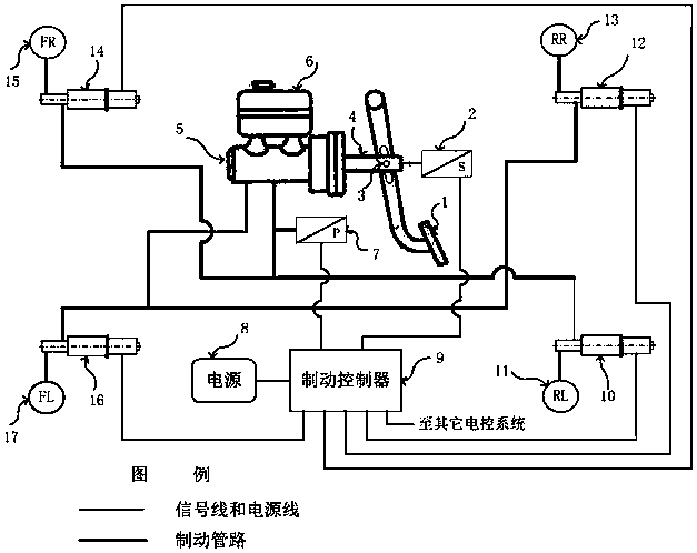
[0074] Such as figure 1 As shown, a distributed composite braking system of the present invention includes a brake pedal 1, a pedal stroke sensor 2, a support pin 3, a push rod 4, a master cylinder 5, a liquid storage tank 6, a master cylinder pressure sensor 7, a power supply 8. Brake controller 9, left rear servo brake cylinder 10, left rear wheel cylinder 11, right rear servo brake cylinder 12, right rear wheel cylinder 13, right front servo brake cylinder 14, right front wheel cylinder 15, left front Servo brake cylinder 16, left front wheel cylinder 17, brake pipeline, signal line and power supply line. The master cylinder 5 is a tandem dual-chamber brake master cylinder. The left rear servo brake cylinder 10, the right rear servo brake cylinder 12, the...


PUM


Abstract

The invention discloses a servo brake cylinder used for a distributed composite brake system, the distributed composite brake system adopting the servo brake cylinder and a brake method of the distributed composite brake system adopting the servo brake cylinder. The servo brake cylinder comprises a shell body, an electromotor, a coupler, a ball screw assembly composed of a nut and a lead screw, abearing, a retainer ring, a piston, a cylinder body and a return spring, wherein an inner hole is formed in the center of the piston, the inner hole comprises a tapered first conical surface, a cylindrical surface and a gradually-expanded second conical surface, the left end of the lead screw extends in the axial direction to sequentially form a tapered third conical surface, a cylindrical surfaceand a gradually-expanded fourth conical surface, the first conical surface cooperates with the fourth conical surface to form an output valve, and the second conical surface cooperates with the thirdconical surface cooperate to form an input valve. According to the servo brake cylinder used for the distributed composite brake system, the distributed composite brake system adopting the servo brake cylinder and the brake method of the distributed composite brake system adopting the servo brake cylinder, the advantages of being compact in structure, flexible in control, high in braking response, high in braking pressure control precision, reliable in failure protection capability, low in manufacturing cost and the like are achieved, so that an intelligent driving automobile is good in motion stability and high in reliability during braking.

Description

technical field [0001] The invention belongs to the technical field of automobile brake systems, and in particular relates to a servo brake cylinder, a brake system and a brake method for a distributed compound brake system. Background technique [0002] In recent years, smart cars have received unprecedented attention and attention. The world's major automobile producing countries and even some countries without an automobile industry have planned and supported the networking and intelligent driving of automobiles as an important strategic direction. According to the division of the International Society of Automotive Engineers, intelligent driving vehicles are divided into five levels, namely, driver assistance (level 1), partial automation (level 2), conditional automation (level 3), high automation (level 4) and full automation (level 4). Level 5). As far as braking systems are concerned, all levels of intelligent driving require the car to have autonomous braking, whi...

Claims


Application Information

Patent Timeline
Patent Type & Authority Applications(China)
IPC IPC(8): F16D65/14F16D121/02F16D127/00
CPCF16D65/14F16D2121/02F16D2127/005
Inventor 邓伟文丁能根
Owner 南京经纬达汽车科技有限公司
Why Eureka
Try Eureka