Distributed braking system with brake pedal travel simulation and failure manual braking functions

A technology of pedal stroke and human braking, applied in the direction of brake safety system, brake transmission device, brake action activation device, etc., can solve the problems of unreliable failure protection ability and slow brake response, etc., and achieve excellent pedal feel , fast dynamic response and small pressure fluctuation

Pending Publication Date: 2021-05-11
南京经纬达汽车科技有限公司
View PDF0 Cites 2 Cited by
  • Summary
  • Abstract
  • Description
  • Claims
  • Application Information

AI Technical Summary

Problems solved by technology

[0005] In order to solve the above-mentioned problems in the prior art, the object of the present invention is to propose a distributed braking system with pedal stroke simulation and invalid manpower backup braking functions, so that the electro-hydraulic servo braking system has an excellent pedal feel and solves the problem of Problems such as compact structure, slow braking response, and unreliable failure protection capability

Method used


Image

  • Distributed braking system with brake pedal travel simulation and failure manual braking functions
  • Distributed braking system with brake pedal travel simulation and failure manual braking functions
  • Distributed braking system with brake pedal travel simulation and failure manual braking functions

Examples


Embodiment 1

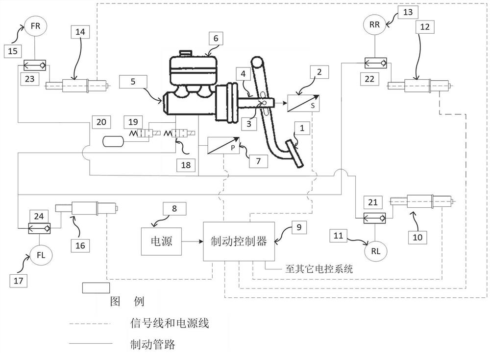
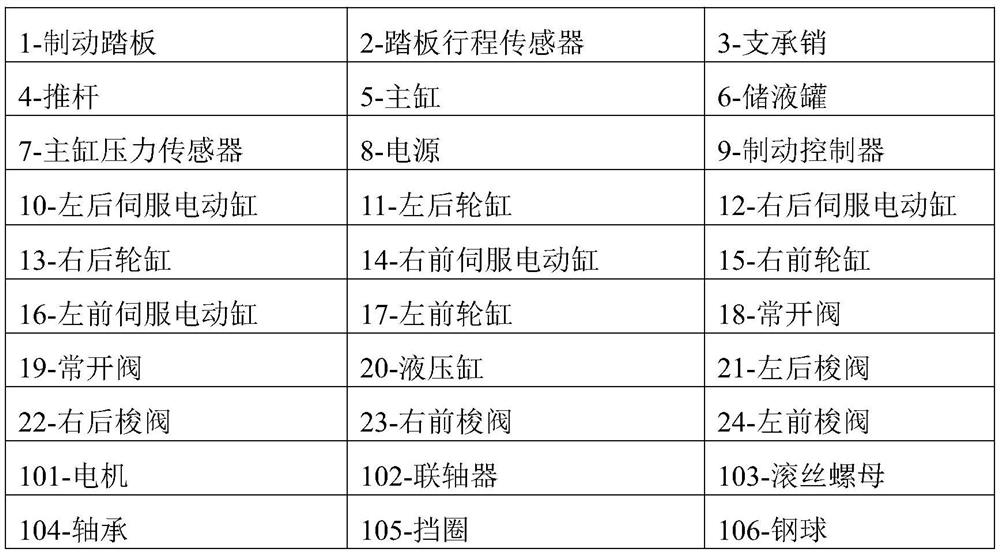
[0043] Such as figure 1 As shown, this embodiment provides a distributed braking system with pedal stroke simulation and failure manpower backup braking function, including a brake pedal 1, a pedal stroke sensor 2, a support pin 3, a push rod 4, a master cylinder 5, Liquid storage tank 6, master cylinder pressure sensor 7, power supply 8, brake controller 9, left rear servo electric cylinder 10, left rear wheel cylinder 11, right rear servo electric cylinder 12, right rear wheel cylinder 13, right front servo electric cylinder 14. Right front wheel cylinder 15, left front servo electric cylinder 16, left front wheel cylinder 17, normally open valve 18, normally closed valve 19, hydraulic cylinder 20, four shuttle valves 21, 22, 23, 24 and brake lines , signal lines and power lines.

[0044] The master cylinder 5 is a tandem dual-chamber brake master cylinder. The left rear servo electric cylinder 10, the right rear servo electric cylinder 12, the right front servo electric c...

Embodiment 2

[0075] The structure of the distributed braking system in this embodiment is basically the same as in Embodiment 1, the difference is that the four brake actuators in this embodiment are arranged in an H shape, and at this time, the left front shuttle valve 24 and the right front shuttle valve 23 One of their oil inlets is connected to the first brake pipeline through parallel pipelines, and their other oil inlets are respectively connected to the left front servo electric cylinder 16 and the right front servo electric cylinder 14; the left rear shuttle valve 21 and the right One oil inlet of the rear shuttle valve 22 is connected to the second brake pipeline through a pipeline in parallel, and the other oil inlet of each of them is respectively connected to the left rear servo electric cylinder 10 and the right rear servo electric cylinder 12 .


PUM


Abstract

The invention discloses a distributed brake system with pedal travel simulation and failure manual backup brake functions. The distributed brake system mainly comprises a brake pedal, a pedal travel sensor, a main cylinder, a normally-closed valve, a normally-open valve, a hydraulic cylinder, a liquid storage tank, a main cylinder pressure sensor, a power source, a brake controller, a shuttle valve, a wheel cylinder and a servo electric cylinder. The on / off of an oil way between the hydraulic cylinder and the main cylinder is achieved through the normally-closed valve and the normally-open valve, so that pedal stroke simulation is achieved, and good pedal feeling is obtained by means of the characteristics that the hydraulic cylinder is large in damping and has hysteresis. By means of the shuttle valve structure, it is ensured that if the power-assisted braking function of the braking system is completely lost due to any fault, manual backup braking can be carried out, and therefore the three working modes of power-assisted braking, active braking and failure manual backup braking are achieved. The distributed brake system has the advantages of compact structure, flexible control, fast brake response, high brake pressure control precision, reliable failure protection capability, low manufacturing cost and the like.

Description

technical field [0001] The invention relates to the technical field of automobile braking, in particular to a distributed braking system with the functions of brake pedal stroke simulation and failure manpower backup braking. Background technique [0002] With the continuous development of automotive electronics, intelligent vehicle systems such as advanced driver assistance systems (ADAS) and automatic driving systems (ADS) have put forward higher braking requirements for automotive braking. Adapt to the needs of modern electric vehicles and smart cars. Since there is no vacuum source provided by the engine on the electric vehicle, a vacuum pump and a vacuum tank are required when this type of vehicle uses vacuum boosting. The disadvantages are that it is noisy, the brake pressure response is slow, and the structure is not compact. Another disadvantage of the traditional vacuum booster braking system is that it is difficult to meet the autonomous braking required by intell...

Claims


Application Information

Patent Timeline
IPC IPC(8): B60T13/74B60T13/14B60T8/40B60T7/08B60T17/18
CPCB60T7/085B60T8/409B60T13/142B60T13/147B60T13/745B60T13/746B60T17/18
Inventor 邓伟文张凯丁能根
Owner 南京经纬达汽车科技有限公司
Why Eureka
Try Eureka