Micro valve capable of controlling liquid flowing and micro flow control chip

A microfluidic chip and liquid flow technology, applied in the direction of fluid controllers, valve devices, engine components, etc., can solve the problems of difficult and precise control of fluid flow, pollution, built-in detection reagents, etc., to simplify steps and external hardware equipment, avoid mutual pollution, simple structure

Active Publication Date: 2018-08-24
LEADWAY HK
View PDF15 Cites 12 Cited by
  • Summary
  • Abstract
  • Description
  • Claims
  • Application Information

AI Technical Summary

Problems solved by technology

This way of simultaneously controlling two kinds of power will make it difficult to precisely control the flow of fluid
Secondly, after the microvalve is opened, the film will be in contact with the fluid, making it impossible to restore the closed state, thus limiting the repeated use of the microvalve structure
This microvalve is only limited to controlling one fluid, and cannot realize the function of controlling multiple fluids at the same time, otherwise the problem of pollution will be unavoidable
In the process of structural overdesign, the above shortcomings can be compensated to a certain extent by optimizing the structure of the film, but this also increases the difficulty of processing and assembling microfluidic chips to a certain extent.
[0005] In the application of microfluidic chips in the field of POCT, another common difficulty in microfluidic chips is how to build detection reagents into the test chip, so as to realize the miniaturization of the entire detection equipment

Method used


Image

  • Micro valve capable of controlling liquid flowing and micro flow control chip
  • Micro valve capable of controlling liquid flowing and micro flow control chip
  • Micro valve capable of controlling liquid flowing and micro flow control chip

Examples


Embodiment Construction

[0079] In the following detailed description, reference texts accompanying the legends are a part hereof and are presented by way of illustration of certain embodiments in which the invention may be practiced. We do not exclude that the present invention can implement other specific solutions and change the structure of the present invention without departing from the scope of use of the present invention.

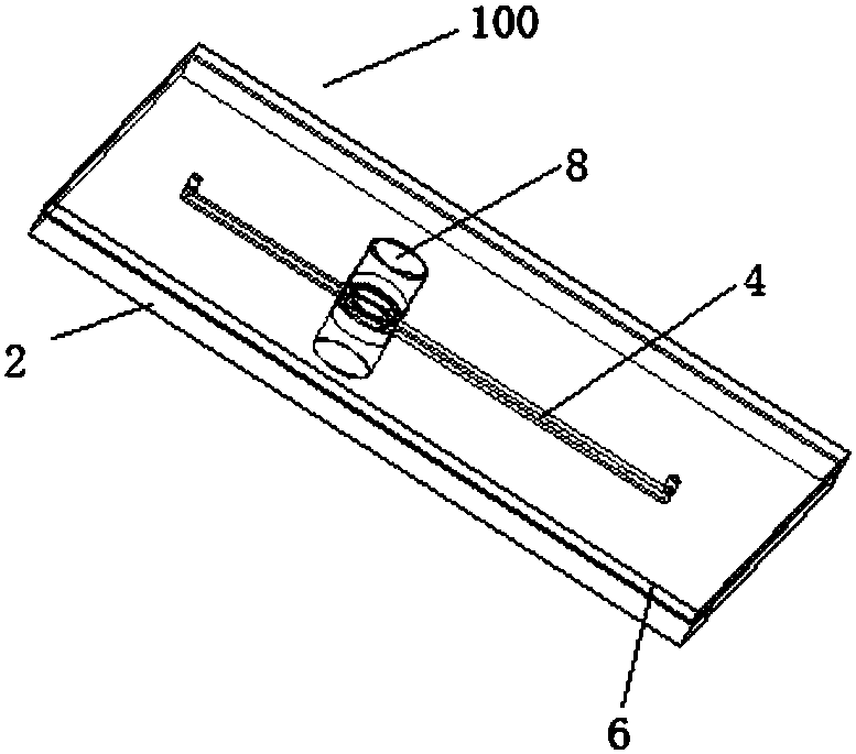
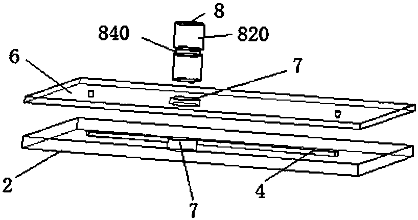
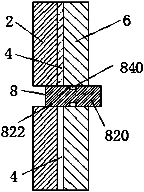
[0080] Such as figure 1 , figure 2 , image 3 with 4 The shown microfluidic chip 100 includes a substrate 2, a microchannel 4 arranged on the substrate, a cover sheet 6 covering the substrate, and a microvalve for controlling the on-off of the microchannel 4 is provided on the channel of the microchannel 4. 8. There is a microvalve socket 7 for installing a microvalve on the chip. The microvalve 8 includes a valve body 820 and a guide channel 840 arranged on the piston. in such as Figures 3 to 4 In the illustrated embodiment, the microvalve is a push-type microvalv...


PUM


Abstract

The invention relates to a micro valve capable of controlling liquid flowing. The micro valve comprises a valve body. The valve body comprises at least two flow guiding channels which are not in communication. The invention further relates to a micro flow control chip. The micro flow control chip comprises a substrate and a cover sheet, and the micro valve capable of controlling liquid flowing anda micro valve inserting hole used for receiving the micro valve are further included. The substrate is provided with a liquid storage groove and a micro channel, and the liquid storage groove and themicro channel are covered with the cover sheet and sealed. The micro channel is connected with the micro valve inserting hole. The micro flow control chip design and the micro flow control micro valve have the beneficial effects that the structure is simple, assembling is convenient, and repeated usage can be achieved; and the structure can be used for long-term effective sealing of a detection reagent in a testing sheet. Meanwhile, due to the flow guiding channels on the micro valve and the micro channel design on the substrate, the situation of flow guiding channel sharing can be avoided, and accordingly, the possibility of mutual pollution between fluid can be avoided.

Description

technical field [0001] The invention belongs to the technical field of medical diagnostic articles, and relates to a microvalve and a microfluidic control chip capable of controlling liquid flow. Background technique [0002] In chemical and biological research, most experiments and test reactions are carried out in solution. At present, there is a research trend that requires smaller and smaller volumes of reaction liquids (sample to be tested and detection reagents), while the same sample has more and more detection items or higher throughput requirements, and can realize the experimental process. Automation and controllability. Microfluidic chips emerged as the times require, and are increasingly used for their characteristics of manipulating smaller volumes of reaction liquids, miniaturization, higher experimental throughput, and automatic control. The microfluidic chip includes a substrate and microchannels arranged in the substrate, and through the synergy of microva...

Claims


Application Information

Patent Timeline
Patent Type & Authority Applications(China)
IPC IPC(8): F16K99/00
CPCF16K99/0003F16K99/0011F16K99/0013F16K99/0028F16K2099/008B01L3/502738F16K2099/0084B01L2300/0874B01L2300/0887B01L2400/0644
Inventor 张歆彭赞标王毅
Owner LEADWAY HK
Why Eureka
Try Eureka