
PMSM (permanent magnet synchronous motor) control device and method based on single current sensor

A technology of permanent magnet synchronous motor and control device, which is applied in the direction of motor generator control, electronic commutation motor control, motor control, etc., can solve the problems of high cost of control device, complicated control method, and large number of sensors, and achieve volume and The effect of cost reduction, avoiding disturbance and ensuring stability

Active Publication Date: 2018-08-24
THE UNIV OF NOTTINGHAM NINGBO CHINA
View PDF3 Cites 7 Cited by
  • Summary
  • Abstract
  • Description
  • Claims
  • Application Information

AI Technical Summary

Problems solved by technology

[0003] In the existing fault-tolerant control of permanent magnet synchronous motors based on single-current sensor technology, two single-current sensors are generally required to collect the current on the remaining two-phase lines that are normally working. The number of sensors is large, and the cost increases. When switching from the normal working state of the permanent magnet synchronous motor to the fault-tolerant control state, the calculation method of current reconstruction needs to be changed. Therefore, the existing permanent magnet synchronous motor control device and control method based on a single current sensor are relatively complicated, and the cost of the control device higher

Method used


Image

  • PMSM (permanent magnet synchronous motor) control device and method based on single current sensor
  • PMSM (permanent magnet synchronous motor) control device and method based on single current sensor
  • PMSM (permanent magnet synchronous motor) control device and method based on single current sensor

Examples


Embodiment Construction

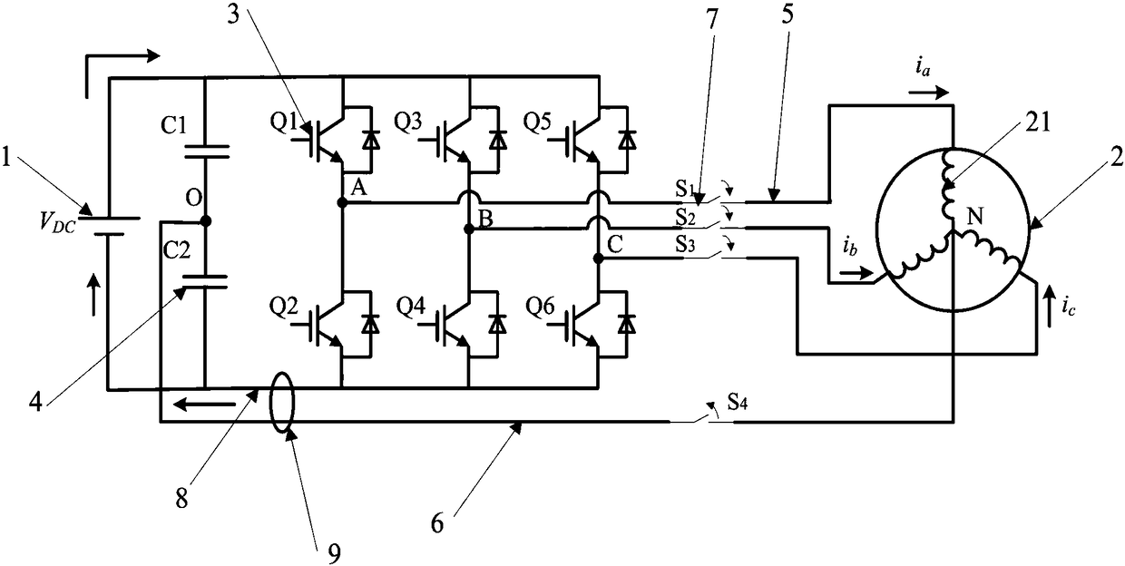
[0027] Such as Figures 1 to 10 As shown, a permanent magnet synchronous motor control device based on a single current sensor includes a permanent magnet synchronous motor 2 connected to a power source 1. The permanent magnet synchronous motor is provided with three-phase windings, which are A phase, B phase and C phase in turn. One end of the three-phase winding intersects at a point N, which is the center point of the three-phase winding 21; outside the power supply, there are four "mouth-shaped" branches in sequence from left to right, and one end of each branch is connected to the power supply 1 connected to the positive pole of the power supply, and the other end is connected to the negative pole of the power supply; the four branches are the voltage dividing branch and the three phase-splitting branches of A phase, B phase and C phase in turn. Two capacitors 4 are provided with inverter switching tubes 3 on each phase-splitting branch of the three-phase branch; each pha...


PUM


Abstract

The invention provides a PMSM (permanent magnet synchronous motor) control device and method based on a single current sensor, and the device comprises a PMSM connected with a power supply. The exterior of the power supply is sequentially provided with four branch lines from the left to the right, and the four branch lines sequentially comprise a voltage dividing branch line and three phase-splitting branch lines. The voltage dividing branch line is provided with two capacitors which are longitudinally adjacent to each other in a width direction, and each of the three phase-splitting branch lines is provided with an inverter switching tube. Each phase-splitting branch line is connected with a three-phase winding in the PMSM through a first wire, and a midpoint between the two capacitors and the midpoint of the three-phase winding are connected through a second wire. The lower ends of the phase-splitting branch lines are connected with the negative electrode of the power supply througha DC bus, and the single current sensor is disposed outside the DC bus and the second wire. The device can achieve the control of the PMSM in a normal operation mode and a fault-tolerant operation mode through one single current sensor, is simple in structure, is simple in control method, and is higher in control efficiency.

Description

technical field [0001] The invention relates to the technical field of permanent magnet synchronous motors, in particular to a control device and control method for permanent magnet synchronous motors based on a single current sensor. Background technique [0002] Compared with other motors, the permanent magnet synchronous motor has the advantages of high reliability, high power density, and high control precision, so it has been rapidly applied in the fields of CNC machine tools, robot servo control, electric vehicles, military weapons, deep-water servo systems, and aerospace. development of. In the entire permanent magnet synchronous motor control system, the inverter switching tube in the three-phase voltage source is a relatively fragile component, and the failure probability of the inverter switching tube is higher than that of the motor itself. When the inverter switching tube fails, the power supply of the phase line is usually cut off, and the remaining two phases ...

Claims


Application Information

Patent Timeline
Patent Type & Authority Applications(China)
IPC IPC(8): H02P21/00H02P21/22H02P25/022
CPCH02P21/0003H02P2205/01H02P2207/05H02P21/22H02P25/024
Inventor 闫浩赵伟铎张何克里斯·杰拉德姜保罗顾春阳徐壮李静王天昊施博闻张天如
Owner THE UNIV OF NOTTINGHAM NINGBO CHINA
Learn More