Power division isolation filter circuit

A technology of isolation filtering and isolation resistance, which is applied in the field of electronics, can solve problems such as electromagnetic compatibility, deterioration of system noise, and large energy of harmonic components, and achieve the effects of improving anti-interference ability, improving system noise, and suppressing harmonic components

Active Publication Date: 2018-08-24
CHINA ELECTRONIC TECH GRP CORP NO 38 RES INST
View PDF4 Cites 0 Cited by
  • Summary
  • Abstract
  • Description
  • Claims
  • Application Information

AI Technical Summary

Problems solved by technology

[0006] The technical problem to be solved by the present invention is that high-power active crystal oscillators usually have large harmonic component energy, which will deteriorate the noise of the entire system and easily cause problems in electromagnetic compatibility

Method used


Image

  • Power division isolation filter circuit
  • Power division isolation filter circuit
  • Power division isolation filter circuit

Examples


Embodiment 1

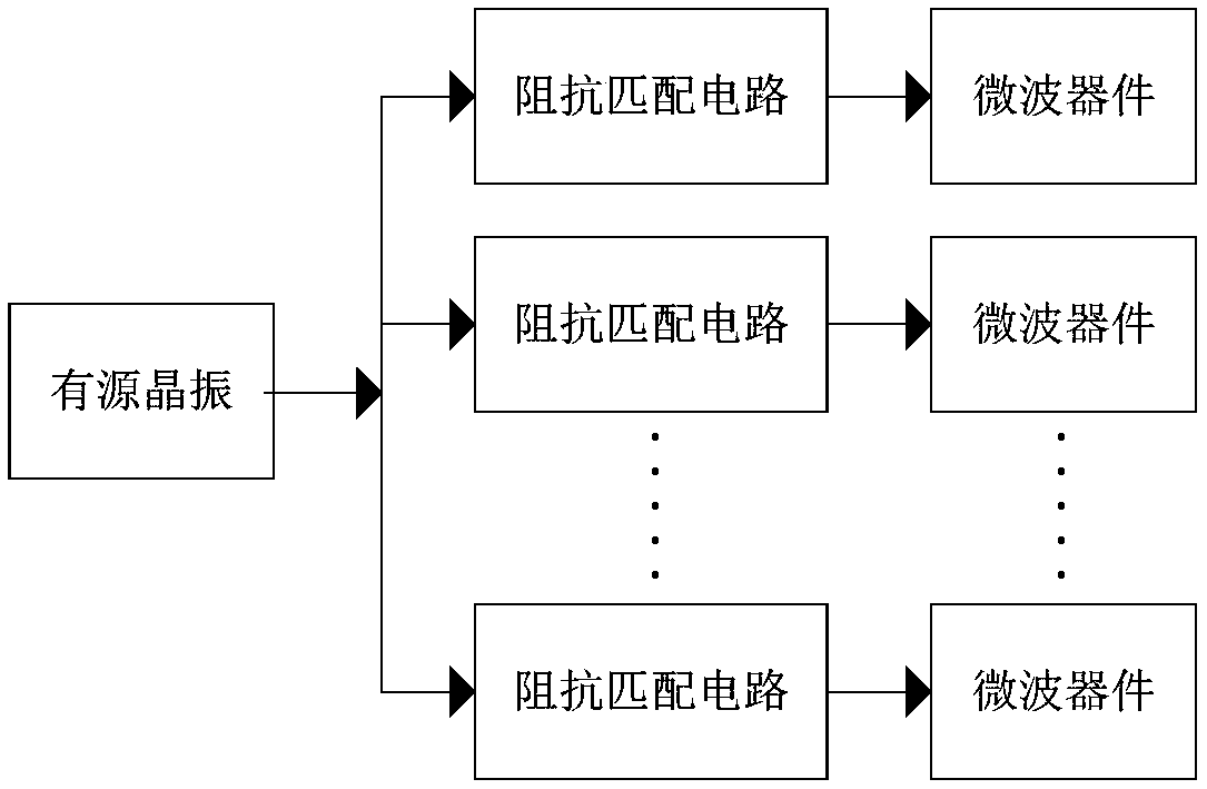
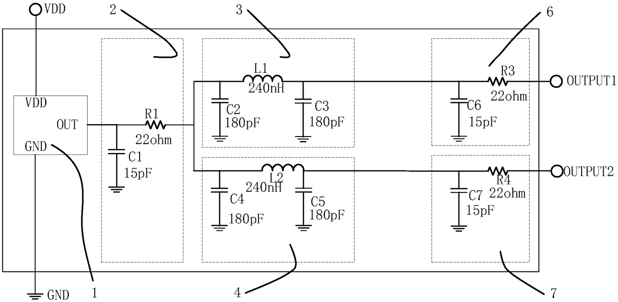
[0028] Such as figure 2 As shown, a power division isolation filter circuit includes: an active crystal oscillator 1, a main port CR matching unit 2, a first CLC filter unit 3, a second CLC filter unit 4, a first CR matching unit 6 and a second CR matching unit Unit 7; the active crystal oscillator 1 is connected to the main port CR matching unit 2, the main port CR matching unit 2 is connected to the input end of the first CLC filter unit 3 and the input end of the second CLC filter unit 4, and the first CLC filter unit 3 The output end of the first CR matching unit 6 is connected to the input end, the output end of the second CLC filter unit 4 is connected to the input end of the second CR matching unit 7, and the output end of the first CR matching unit 6 is connected to the circuit output end OUTPUT1 The output end of the second CR matching unit 7 is connected to the circuit output end OUTPUT2.

[0029] Specifically, the main port CR matching unit 2 includes a capacitor ...

Embodiment 2

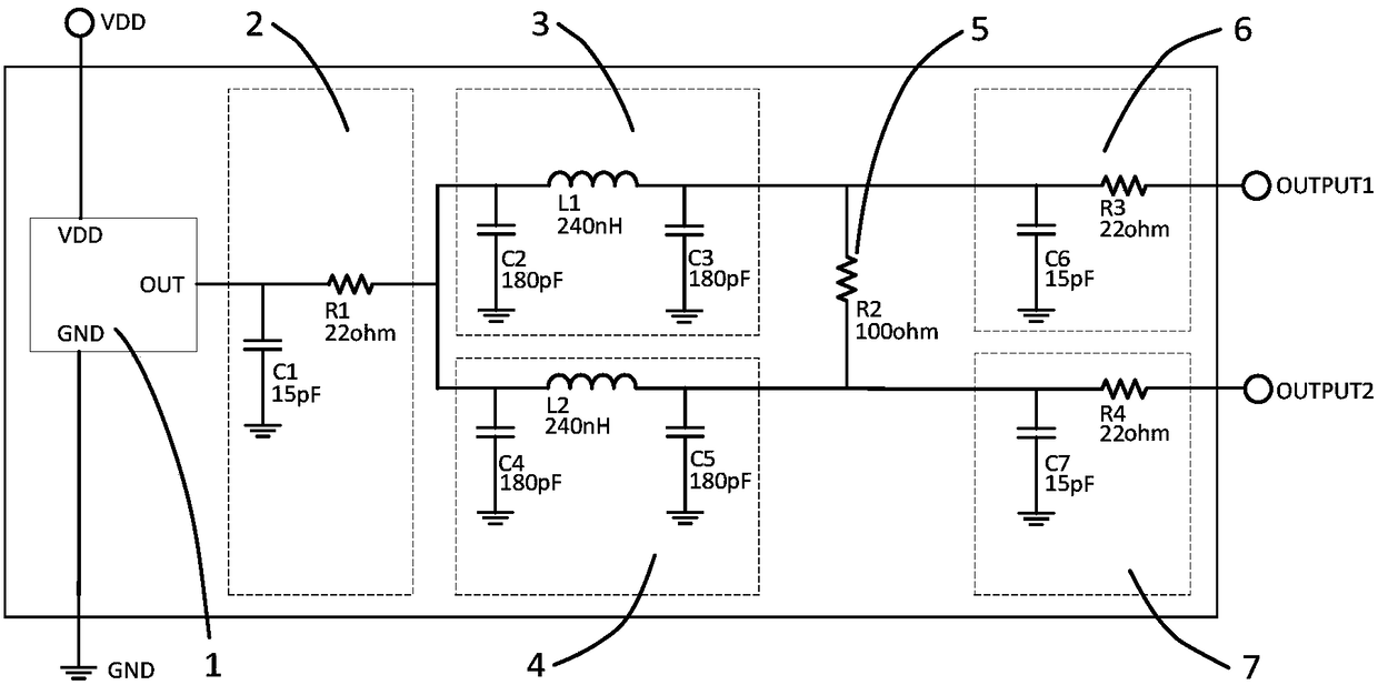
[0038] Such as image 3 As shown, the difference between Embodiment 2 and Embodiment 1 is that: the output end of the first CLC filter unit 3 and the output end of the second CLC filter unit 4 are connected through an isolation resistor 5, and the first CR matching unit 6 and the second CR matching The unit 7 is also connected through the isolation resistor 5, that is, one end of the isolation resistor 5 is connected to one end of the capacitor C3 of the first CLC filter unit 3 and the other end of the inductor L1, and one end of the capacitor C6 of the first CR matching unit 6 and one end of the resistor R3 Connection; the other end of the isolation resistor 5 is connected with one end of the capacitor C5 of the second CLC filter unit 4 and the other end of the inductor L2, one end of the capacitor C7 of the second CR matching unit 7 and one end of the resistor R4, when there is a clutter signal When entering the circuit of the present invention from the circuit output termin...

Embodiment 3

[0040] Such as Figure 4 As shown, the difference between the third embodiment and the first embodiment is that the circuit output terminal OUTPUT1 and the circuit output terminal OUTPUT2 can be connected to the first CLC filter unit, the second CLC filter unit, the first CR matching unit and the second CR matching unit. The power division isolation filter circuit uses a cascading method to increase the output terminal of the active crystal oscillator signal, thereby connecting multiple microwave integrated devices, making the power division isolation filter circuit more widely used.

[0041] In summary, the embodiment of the present invention provides a power division isolation filter circuit through the matching unit and the filter unit to solve the problems of poor anti-interference ability and inability to optimize the system noise of the existing clock shunt circuit, which can be effectively applied to automobile collision avoidance In the radar system, the radar performa...


PUM


Abstract

The invention discloses a power division isolation filter circuit, which relates to the technical field of electronics. The power division isolation filter circuit comprises an oscillator, a general port CR matching unit, a first CLC filter unit, a second CLC filter unit, a first CR matching unit and a second CR matching unit; the oscillator is connected with the general port CR matching unit, thegeneral port CR matching unit is connected with an input end of the first CLC filter unit and the input end of the second CLC matching unit, the output end of the first CR matching unit is connectedwith a first output end of the circuit, the output end of the second CR matching unit is connected with a second output end of the circuit. The power division isolation filter circuit provided by theinvention has the advantages of realizing isolation and filtering of output shunt signals of the oscillator, enhancing interference resistance and reducing system noise.

Description

technical field [0001] The invention relates to the field of electronic technology, and more specifically relates to a power division isolation filter circuit. Background technique [0002] In recent years, microwave integrated devices have developed rapidly, and the degree of integration and digitization has continued to deepen, and microwave devices that require time signals are increasing. In the coherent system application, the clock signal of each microwave integrated device must be synchronized, and the signal quality cannot be deteriorated, which puts forward higher requirements for the clock shunt circuit. [0003] The usual practice is as figure 1 As shown, it is to select a high-power active crystal oscillator, provide a clock signal that meets the requirements, and directly divide the output into multiple channels, and each signal is connected to the corresponding device after impedance matching. This method can meet the power requirements of the clock signal, e...

Claims


Application Information

Patent Timeline
Patent Type & Authority Applications(China)
IPC IPC(8): H03H7/01
CPCH03H7/1725
Inventor 卢绍英孙元峰邹敏张飞飞杨黔王泽忠曹佳男马凯英
Owner CHINA ELECTRONIC TECH GRP CORP NO 38 RES INST
Why Eureka
Try Eureka