

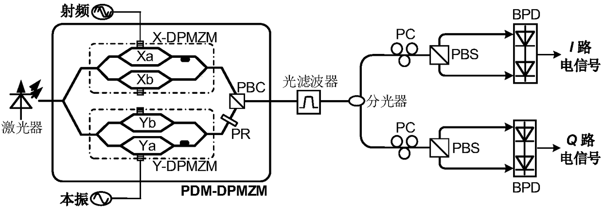
Photonics microwave I/Q down-conversion system
A frequency conversion system, photonics technology, applied in electromagnetic wave transmission system, transmission system, electromagnetic transmitter and other directions, can solve the problems of limited system bandwidth and I/Q balance, avoid frequency dependence, strong operability , the effect of simple structure
- Summary
- Abstract
- Description
- Claims
- Application Information
AI Technical Summary
Problems solved by technology
Method used
Image

Examples
Embodiment 1
[0054] Embodiment 1: the laser wavelength that the selected laser produces is 1552.3nm, and optical power is 17dBm; The radio frequency signal that the radio frequency signal source produces frequency 26GHz, power 0dBm; The local oscillator signal that the local oscillator signal source produces frequency 25.9GHz, power 10dBm; PDM- The half-wave voltage of DPMZM is 3.5V, the bandwidth is 30GHz, and the extinction ratio is 30dB; the center wavelength of the optical filter is 1552.6nm, and the 3dB bandwidth is 0.6nm; the 3dB response bandwidth of BPD is 1GHz, and the responsivity is 1.1A / W;
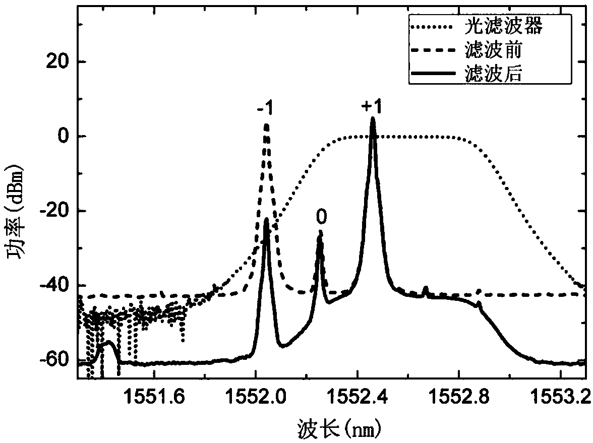
[0055] Test the passband curve of the optical filter, see figure 2 ;
[0056] Adjust the output voltage of the DC voltage source so that the sub-modulators Xa, Xb, Ya, and Yb all work at the minimum point. At this time, the optical signal input to the optical filter mainly includes ±1-order sidebands, carrier and even-order sidebands that are suppressed Optical signal, spectrum see figu...
Embodiment 2
[0060] Embodiment 2: the laser wavelength that the selected laser produces is 1552.3nm, and optical power is 17dBm; The radio frequency signal that the radio frequency signal source produces frequency 36GHz, power 0dBm; The local oscillator signal that the local oscillator signal source produces frequency 17.95GHz, power 18dBm; PDM- The half-wave voltage of DPMZM is 3.5V, the bandwidth is 30GHz, and the extinction ratio is 30dB; the center wavelength of the optical filter is 1552.6nm, and the 3dB bandwidth is 0.6nm; the 3dB response bandwidth of BPD is 1GHz, and the responsivity is 1.1A / W;
[0061] Test the passband curve of the optical filter, see Figure 4 ;
[0062] Adjust the output voltage of the DC voltage source so that the sub-modulators Xa and Xb work at the minimum point, Ya works at the maximum point, Y-DPMZM works at the minimum point, and adjust the Yb working point so that the optical carrier output by the Y-DPMZM is suppressed; at this time The optical signal i...
PUM
 Abstract
Description
Claims
Application Information