
Method and system for marking image acquisition time

An image acquisition and timing technology, applied in image communication, components of TV systems, components of color TVs, etc. The effect of reducing errors and improving practicality

Active Publication Date: 2019-12-03
BEIJING INSTITUTE OF TECHNOLOGYGY
View PDF5 Cites 0 Cited by
  • Summary
  • Abstract
  • Description
  • Claims
  • Application Information

AI Technical Summary

Problems solved by technology

For example, in the experimental study of the stick-slip dynamic process of rock structures, the transient process of rock fault failure is on the order of ten microseconds, and the start-up time difference of hundreds of microseconds between two high-speed cameras makes it difficult for the two cameras to collect each image. The moment of time is "misplaced" on the time axis, distorting the final measurement result
[0008] In addition, during the entire image acquisition process, the time interval between two adjacent images is not strictly uniform, which is called "travel time error" here, that is, the above assumption (2) is not strictly established
For example, for a low-speed camera controlled by software trigger mode, due to low precision and stability, the collected images will have travel time errors

Method used


Image

  • Method and system for marking image acquisition time
  • Method and system for marking image acquisition time
  • Method and system for marking image acquisition time

Examples


Embodiment 1

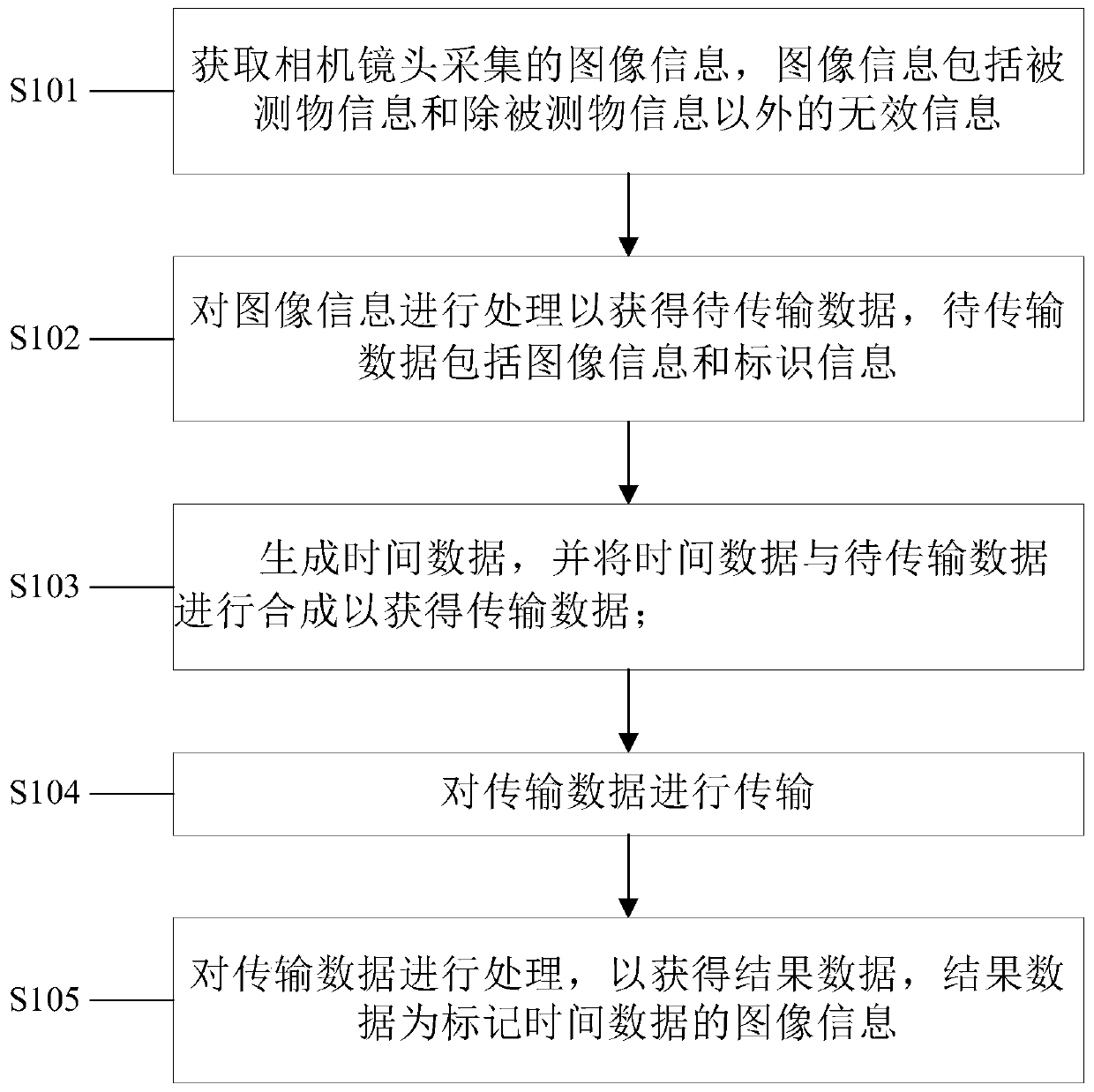
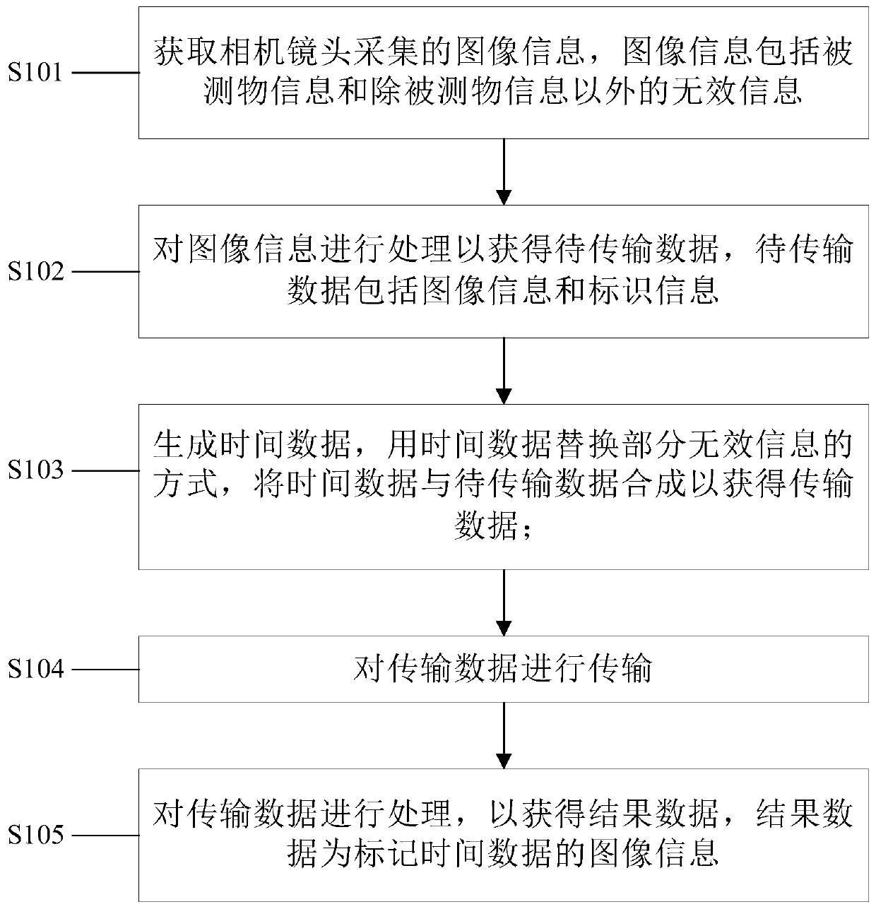
[0060] figure 1 It is a flow chart of a method for marking the moment of image collection in an embodiment of the present invention. See figure 1 , a method for marking an image acquisition moment, comprising:

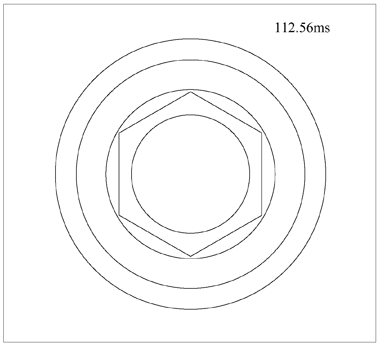
[0061] Step S101: Obtain the image information collected by the camera lens, the image information includes the measured object information and invalid information except the measured object information. Usually, the measured object information is in the central area of ​​the image, and the invalid information surrounds the measured object information, because the definition of the central area of ​​the image is higher than that of the edge area.

[0062] Step S102: Process the image information to obtain data to be transmitted, the data to be transmitted includes image information and identification information, the identification information includes frame identification information and line identification information, and the frame identification information is us...

Embodiment 2

[0076] In order to solve the above technical problems, the present invention also proposes a system for marking the time of image collection, Image 6 It is a schematic structural diagram of a system for marking image acquisition time in an embodiment of the present invention, please refer to Image 6 , the system for marking the moment of image acquisition, comprising:

[0077] The image sensor 1 acquires the image information collected by the camera lens, and the image information includes the measured object information and invalid information except the measured object information;

[0078] The image integration module 2, coupled with the image sensor 1, processes the image information to obtain data to be transmitted, the data to be transmitted includes image information and identification information, the identification information includes frame identification information and row identification information, and the frame identification information is used for Define the ...

Embodiment 3

[0092] The method and system for marking the moment of image acquisition provided by the present invention can be used to calibrate the acquisition moment when at least two cameras are used for image acquisition. The measured object is collected to obtain multi-directional images of the measured object. However, there is usually a time difference between the collection times of multiple cameras, thus causing images from different directions collected at different times to be taken at the same time. , which may cause errors in later data analysis. Among them, multiple cameras are divided into a master camera and at least one slave camera, the master and slave are only relative, and the camera can be freely selected as the master camera according to actual needs. Once the master camera is determined, the time data generated by the clock module of this camera is considered as the standard time, and the time of the slave camera is corrected according to the time of the master came...


PUM


Abstract

The invention discloses a method and system for marking the time of image collection. The method includes: acquiring image information collected by a camera lens, the image information including measured object information and invalid information except the measured object information; processing the image information to Obtain the data to be transmitted, the data to be transmitted includes image information and identification information, and the identification information includes frame identification information and line identification information; generate time data, and combine the time data with the data to be transmitted to obtain transmission data; transmit the transmission data ; Process the transmission data to obtain result data, which is image information of time-marked data. The invention synthesizes the generated time data and the data to be transmitted, and can accurately mark the acquisition time of the image; it does not affect the image acquisition of the measured object, and at the same time, it does not affect the measured object; it can be applied to high temperature and high wind speed , high humidity and other harsh testing environments, with strong practicability.

Description

technical field [0001] The present invention relates to the technical field of image acquisition, and more specifically, to a method and system for marking the moment of image acquisition. Background technique [0002] The camera is a commonly used image acquisition device in the fields of industrial production and scientific research. It is often used to collect the dynamic process of the measured object. By analyzing the collected images, qualitative or quantitative measurement results are obtained. This process is called Image measurement. In modern image measurement applications, most of them are cosecant four-dimensional (x, y, z, t) measurements. The dimension t in the formula is the measurement time. If there is no accurate measurement time as a benchmark, it is impossible to achieve an accurate four-dimensional measurement. The accuracy of the acquisition time will directly affect the accuracy of the final image measurement results. Visible time measurement occupie...

Claims


Application Information

Patent Timeline
Patent Type & Authority Patents(China)
IPC IPC(8): H04N5/247H04N1/32H04N23/90
CPCH04N1/32101H04N1/32144H04N23/90
Inventor 刘振宇汪亮王超乔志正马沁巍马少鹏
Owner BEIJING INSTITUTE OF TECHNOLOGYGY
Learn More