A system and method for precisely locating data collection time
A technology of data acquisition and precise positioning, which is applied in elastic testing, testing of machines/structural components, instruments, etc. It can solve problems such as misstored data, loose establishment, and lost data, so as to achieve high measurement accuracy and avoid measurement less precise effects
- Summary
- Abstract
- Description
- Claims
- Application Information
AI Technical Summary
Problems solved by technology
Method used
Image
Examples
Embodiment 1
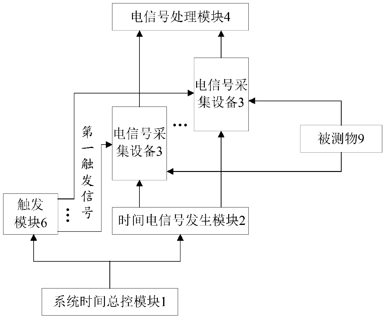
[0082] figure 1 It is a system for precisely locating the time of data collection in Embodiment 1 of the present invention. See figure 1 The system for accurately locating the time of data collection provided in this embodiment includes: a system time master control module 1, a time electrical signal generation module 2, at least one electrical signal acquisition device 3, an electrical signal processing module 4, a trigger module 6 and a measured Object 9.
[0083] The system time master control module 1 provides a reference time, and sends the reference time to the time electrical signal generation module 2 and the trigger module 6 .
[0084] The time electrical signal generation module 2 is coupled with the system time master control module 1, receives the reference time, and generates at least one time electrical signal based on the reference time. The time electrical signal is an electrical signal that changes with time according to a specific rule, and each time electr...
Embodiment 2
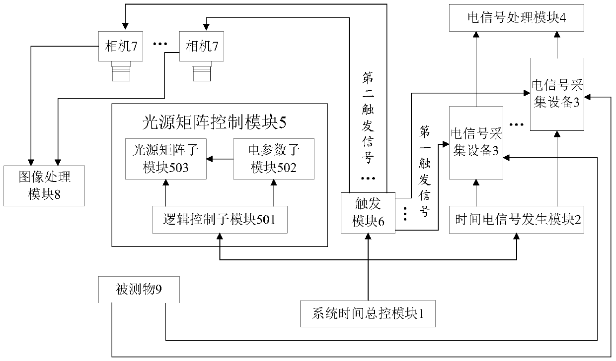
[0091] figure 2 It is a system for precisely locating the time of data collection in Embodiment 2 of the present invention. See figure 2 The system for accurately locating the time of data collection provided in this embodiment includes: a system time master control module 1, a time electrical signal generation module 2, at least one electrical signal acquisition device 3, an electrical signal processing module 4, a trigger module 6 and a measured Object 9 and image acquisition and processing subsystem, including light source matrix control module 5, camera 7 and image processing module 8.
[0092] The system time master control module 1 provides a reference time, and sends the reference time to the time electrical signal generation module 2 and the trigger module 6;
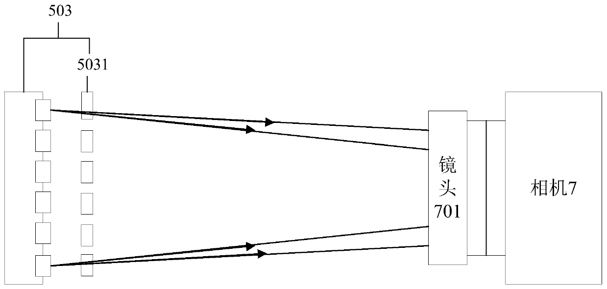
[0093]The time electrical signal generation module 2 is coupled with the system time master control module 1, receives the reference time, and generates at least one time electrical signal based on the refer...
Embodiment 3
[0109] Figure 4 It is a flowchart of a method for precisely locating data collection time in Embodiment 3 of the present invention. See Figure 4 , the method for precisely locating the data collection moment in this embodiment includes:
[0110] Step S101: system installation steps, including:
[0111] The system time master control module is respectively coupled with the electrical signal generation module and the trigger module, the electrical signal generation module and the trigger module are respectively coupled with the electrical signal acquisition equipment, and the electrical signal acquisition equipment is respectively connected with the measured object and the electrical signal The processing device is coupled, and there is at least one electrical signal acquisition device, wherein the measured object includes the measured object body and at least one sensing unit, the sensing unit is associated with the measured object body, and the sensing unit conducts the me...
PUM
 Abstract
Description
Claims
Application Information
 - R&D
- Intellectual Property
- Life Sciences
- Materials
- Tech Scout
- Unparalleled Data Quality
- Higher Quality Content
- 60% Fewer Hallucinations
Browse by: Latest US Patents, China's latest patents, Technical Efficacy Thesaurus, Application Domain, Technology Topic, Popular Technical Reports.
© 2025 PatSnap. All rights reserved.Legal|Privacy policy|Modern Slavery Act Transparency Statement|Sitemap|About US| Contact US: help@patsnap.com


