
A method for installing vertical splicing joints of steel plate concrete shear walls

A technology of steel plate concrete and installation method, applied in the direction of walls, buildings, building components, etc., can solve the problems of increasing construction difficulty and danger, end plates affecting building use, weak controllability of splicing quality, etc., and achieving vertical splicing man-hours. The effect of shortening, shear and tensile force transmission is reliable, and the production complexity is reduced

Inactive Publication Date: 2020-03-27
TIANJIN UNIV
View PDF6 Cites 0 Cited by
  • Summary
  • Abstract
  • Description
  • Claims
  • Application Information

AI Technical Summary

Problems solved by technology

[0005] (1) Splicing is carried out by reserving grouting holes and extending steel bars, which still requires wet construction, and the controllability of splicing quality is weak after a long time
[0006] (2) The end of the column is provided with an end plate that is spliced ​​by bolts, the production and processing are complicated, and the end plate affects the use of the building
[0007] (3) The prefabricated extension members at the end of the column are spliced ​​by welding, which requires the use of open flames, which increases the difficulty and risk of construction, and the weld quality is less controllable

Method used


Image

  • A method for installing vertical splicing joints of steel plate concrete shear walls
  • A method for installing vertical splicing joints of steel plate concrete shear walls
  • A method for installing vertical splicing joints of steel plate concrete shear walls

Examples


Embodiment Construction

[0037] The specific implementation manners of the present invention will be described in detail below in conjunction with the accompanying drawings.

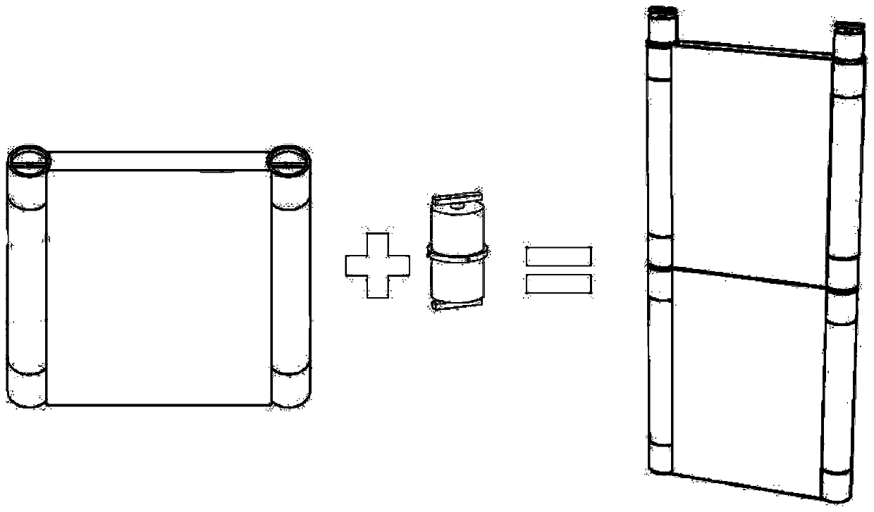
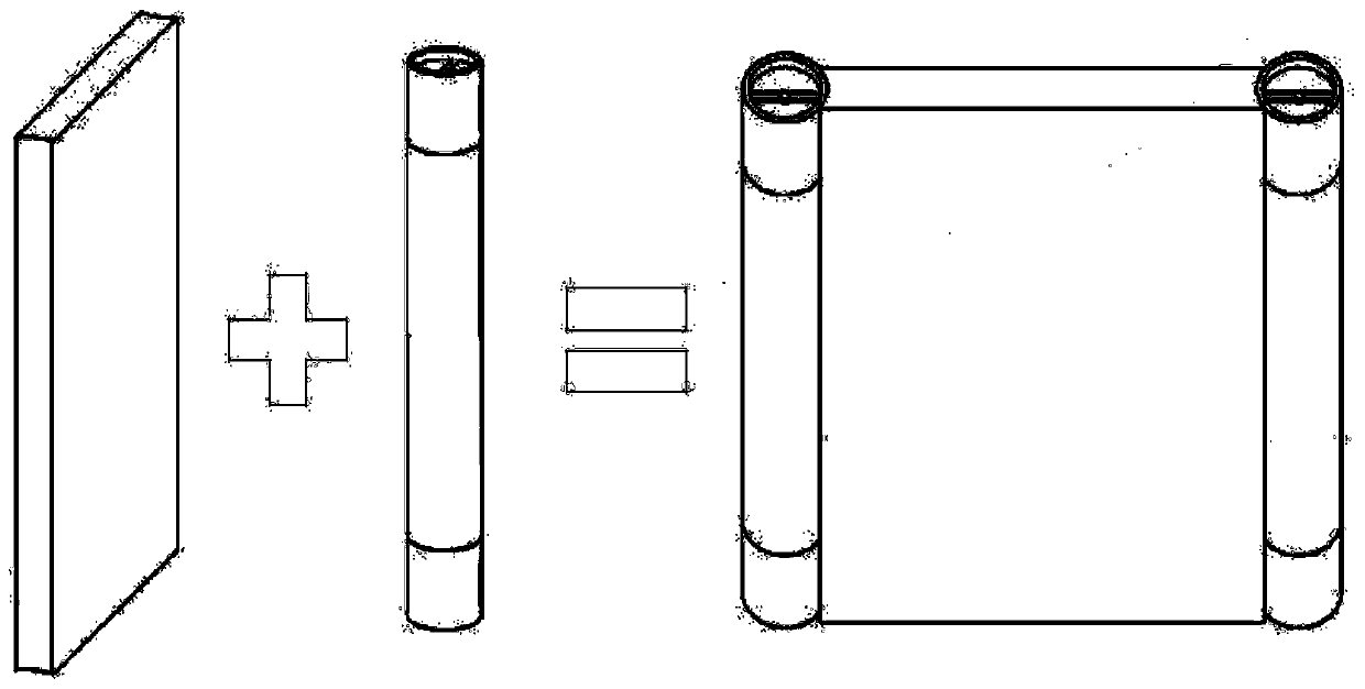
[0038] A kind of steel plate concrete shear wall vertical splicing node installation method of the present invention as shown in the accompanying drawing, comprises the following steps:

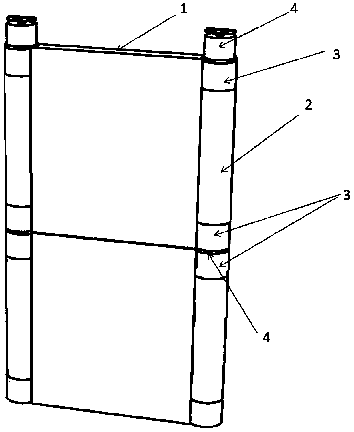
[0039] (1) Prefabricate the steel plate concrete shear wall 1, steel plate concrete shear wall end column 2, joint joint end 3 and shear tie 4 respectively in the factory, where the joint joint end and shear tie can be cast cast steel;

[0040] The steel plate concrete shear wall end column 2 is a circular pipe column, and the splicing node end 3 includes an end pipe column with the same outer diameter as the circular pipe column, and the space between the end pipe column The lower part of the cavity 12 is welded with a horizontal steel plate 10 along the horizontal direction, and an installation groove 11 is opened on the horizontal steel pla...


PUM


Abstract

The invention discloses an installation method for vertical splice joints of steel plate concrete reinforced concrete shear walls. The installation method includes the following steps that (1) the steel plate reinforced concrete shear walls, steel plate reinforced concrete shear wall end posts, splice joint end heads and shear resistance tension parts are separately prefabricated in a factory; (2)splice joint end heads are welded to the upper and lower ends of the steel plate concrete reinforced concrete shear wall end posts separately; (3) the steel plate concrete reinforced concrete shear wall end posts with the splice joint end heads in a welded mode are welded to the left and right sides of each steel plate reinforced concrete shear wall separately to form connecting walls; (4) the lower piece connecting walls are hoisted to the preset positions to be vertical; and (5) upper piece connecting walls and the lower piece connecting walls are connected. The installation method for thevertical splice joints of the steel plate concrete reinforced concrete shear walls has the advantages of shearing resistance and tension resistance and reliable force transferring, and can bear high tension and shear force load.

Description

technical field [0001] The invention relates to a vertical splicing node of an assembled prefabricated steel plate concrete shear wall end column, in particular to a method for installing a vertical splicing node of a steel plate concrete shear wall. Background technique [0002] Under the background of creating a "resource-saving and environment-friendly" society, the steel plate concrete shear wall has high bearing capacity, good ductility and stable hysteretic performance. Compared with the traditional concrete shear wall, no formwork is required , The construction speed is fast and the wall is thin, which can effectively reduce the self-weight of the structure to a certain extent. [0003] The steel plate concrete shear wall with end columns is the most common form of steel plate concrete shear wall. Since the steel plate concrete shear wall mainly considers the force in its plane, combined with its structural characteristics, the horizontal load can be applied to the pl...

Claims


Application Information

Patent Timeline
Patent Type & Authority Patents(China)
IPC IPC(8): E04B2/56E04B2/60
CPCE04B2/56E04B2/60
Inventor 严加宝谢文俊王哲董昕严炎炎
Owner TIANJIN UNIV
Learn More