
Solar air conditioner device

An air conditioner and solar energy technology, which is applied in the directions of solar thermal energy, solar collector, solar heating system, etc., can solve the problems of large power consumption, damage, inability to realize automatic control and storage of air conditioners, etc., and achieves convenient operation and simple structure. Effect

Inactive Publication Date: 2018-08-28
阮哲栋
View PDF0 Cites 0 Cited by
  • Summary
  • Abstract
  • Description
  • Claims
  • Application Information

AI Technical Summary

Problems solved by technology

[0002] At present, with the continuous improvement of people's living standards, the use of air conditioners is becoming more and more extensive. Due to the large power consumption of air conditioners, solar air conditioners have gradually replaced the use of commercial power. The most commonly used solar energy conversion is photovoltaic panels. The solar photovoltaic panels are usually fixed, and cannot effectively adjust the orientation according to the rotation and revolution of the earth, so the solar energy conversion efficiency is low, and the traditional solar photovoltaic panels are directly exposed and fixed on the fixed frame. This structure is extremely vulnerable to wind and Due to the influence of climatic factors such as sand and dust, it will cause damage, and the automatic control of storage work cannot be realized.

Method used


Image

  • Solar air conditioner device
  • Solar air conditioner device
  • Solar air conditioner device

Examples


Embodiment Construction

[0014] Combine below Figure 1-4 The present invention will be described in detail.

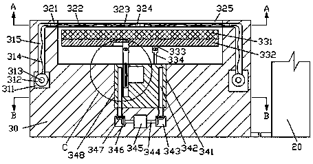
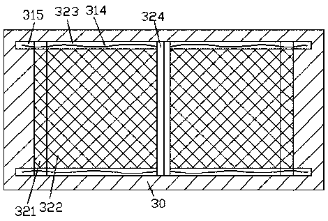
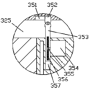
[0015] refer to Figure 1-4 , according to an embodiment of the present invention, a solar air-conditioning device includes a mounting frame 30 and an air-conditioning body 20, and an accommodating cavity 325 is arranged in the top end surface of the mounting frame 30, and the upper sides of the inner walls of the front and rear sides of the accommodating cavity 325 are The first sliding groove 323 is symmetrically provided at the center, and the inner walls of the left and right sides of the receiving chamber 325 are symmetrically provided with the receiving chamber 321 communicated with the first sliding groove 323. Slot 315, the extended end of the bottom of the L-shaped groove 315 communicates with the first rotating groove 311, the first sliding groove 323 between the front and rear sides is slidingly fitted with a connecting rod 324, and the outer side of the connecting rod 342 A stay...


PUM


Abstract

The invention discloses a solar air conditioner device which comprises a mounting rack and an air conditioner body. A containing cavity is formed in the top end face of the mounting rack, first sliding grooves are symmetrically formed in the upper sides in the inner walls on the front side and the rear side of the containing cavity, and storage cavities communicating with the first sliding groovesare symmetrically formed in the inner walls of the left side and the right side of the containing cavity. L-shaped grooves are formed in the outer sides of the storage cavities in a front-back symmetrical mode. The extension tail ends of the bottoms of the L-shaped grooves are provided with first rotating grooves in a communicating mode. A connection rod is installed in the portion, between the front side and the rear side, of each first sliding groove in a sliding fit mode. A pull rope is fixedly installed in the portion, on the outer side of the corresponding connection rod, of each first sliding groove. The pull ropes extend into the L-shaped grooves and the first rotating grooves in sequence to be fixedly connected with rope take-up rotary drums in the first rotating grooves. A firstrotating shaft is fixedly installed between the rope take-up rotary drums on the front side and the rear side. The first rotating shaft is connected with the mounting rack in a rotary fit mode and isdriven through a motor.

Description

technical field [0001] The invention relates to the field of new energy technology, in particular to a solar air conditioner. Background technique [0002] At present, with the continuous improvement of people's living standards, the use of air conditioners is becoming more and more extensive. Due to the large power consumption of air conditioners, solar air conditioners have gradually replaced the use of commercial power. The most commonly used solar energy conversion is photovoltaic panels. The solar photovoltaic panels are usually fixed, and cannot effectively adjust the orientation according to the rotation and revolution of the earth, so the solar energy conversion efficiency is low, and the traditional solar photovoltaic panels are directly exposed and fixed on the fixed frame. This structure is extremely vulnerable to wind and Due to the influence of weather factors such as sand and dust, the damage is caused, and the automatic control of storage cannot be realized. ...

Claims


Application Information

Patent Timeline
Patent Type & Authority Applications(China)
IPC IPC(8): F24F5/00F24S30/425F24S30/20H02S30/20H02S20/32
CPCF24F5/0046F24F2005/0067H02S20/32H02S30/20Y02E10/50
Inventor 阮哲栋
Owner 阮哲栋
Learn More